4550T Configuration for PBX use
Usually, we'll create two independent Virtual LANs (VLANs) on the switch, one for the ELAN, and one for the TLAN. With newer switch firmware, its possible to enable routing from one virtual LAN to another. This has the advantage on enabling access to the TLAN from the ELAN, for example to administer BCM's hooked to the TLAN.
- Connect a Serial cable to the front panel Console port, set a PuTTY (or Serial for OSX) to: 9600-8N1
- Power up, and watch the console output during boot up.
- At the Avaya logo, press
Ctrl-y, followed byen
Check the current firmware version with show sys-info, and perform a Firmware Upgrade if required.
Factory Reset the switch: enter restore factory-default, and confirm. The switch will re-boot.
If a password is required but not known, see: Reset to Factory Defaults.
Setup:
- At the Avaya logo, press
Ctrl-y, followed byen - Type
installto launch the set-up utility - Enter:
- IP address (Management)
- Sub-Net
- Gateway
- enter through all others - Disconnect serial cable, plug LAN into Port 1
- Enter the Management IP in a PC browser window
Now we can continue using the web interface... (use Port 1 as the management port)
Note: The web interface is compatible with Internet Explorer versions 8.x and 9.x, or Mozilla Firefox 23.x
To access the web interface from a Mac, use an old version of firefox, such as Firefox 3.6.28 
Stack Configuration
Connect Baystacks in Stack Configuration and power up Non Base Units first!
Power up Base Unit (set switch on rear to BASE first, in Cab 0) and wait three minutes, if CNTL+Y is entered before time is up, it will set as Switch IP
Cntl+Y, initiate Baystack Stack Config NO MENU SELECTIONS AT ANY POINT
Set lead parameters:
- IN BAND IP (defaults to Stack IP, if you waited three minutes after initial boot)
- Enter SUBNET MASK IP
- Enter DEFAULT GATEWAY IP
- SKIP Community String Public
- SKIP Community String Private
- MUST DO QUICK START VLAN [1]:1 (Must enter 1 to get access to IP GUI)
- 4550T> EXIT
Change Stack IP Address
- Change PC or Laptop IP Scheme to match Baystack Stack subnet.
- Place Ethernet cable into PC and preferred odd number port of Baystack.
- Open a browser window, and enter the IP address of the Stack IP to access the web GUI.
- Go to CONFIGURATION, IP, DISABLE BOOTP and update IP Scheme
- Continue to separate the V LAN and T LAN
Separate the V LAN and T LAN
- CONFIGURATION ➤ PORT MANAGEMENT ➤ ensure AUTO-NEGOCIATE is ENABLED (default)
- APPLICATIONS ➤ VLAN ➤ VLAN CONFIGURATION
- Under VLAN Table, select ACTION Notepad (NOT the X)
- Enter VLAN 1 Name "ELAN"
- Deselect all EVEN ports in Ports Membership
- Press Submit
- Select CREATE VLAN
- VLAN, enter 2
- VLAN Name, enter TLAN
- Press Submit
- Change VLAN CONFIG CONTROL SETTING to AUTO PVID
- Press Submit
- Under VLAN Table, select TLAN ACTION Notepad (NOT the X)
- Select all EVEN ports in Ports Membership
- Press Submit
- APPLICATIONS ➤ VLAN, VLAN PORT CONFIGURATION ➤ ensure TAGGING is set to UNTAG ALL (default)
- APPLICATIONS ➤ SPANNING TREE ➤ PORT CONFIGURATION ➤ Change PARTICIPATION to NORMAL LEARNING by setting SWITCH and STACK to NORMAL LEARNING, check the box and Press Submit. DEFAULT has PARTICIPATION to NORMAL LEARNING ON ODD PORTS
- ADMINISTRATION ➤ RESET ➤ reset entire stack ➤ YES
Activate Routing (optional)
To activate routing (between E and T-LANs), make sure you're at the latest firmware, then follow these steps. Hit "Apply" after each change.
VLAN ➤ SETTINGS ➤ make sure autopvid is set
VLAN ➤ TLAN ➤ SETTINGS ➤ assign ip address (match ELAN for consistency)
VLAN ➤ TLAN ➤ SETTINGS ➤ (scroll way right) set routing to TRUE
IP ROUTING ➤ IP ➤ turn on forwarding
Once the switch is set, make tunnels to get from place to place.
Configuration Backup
From the TTY, issue the following commands (with a TFTP server running on 10.10.10.1):
save config
copy running tftp address 10.10.10.1 filename ers.cfg
Alternatively, backup to a USB thumb drive plugged into the front panel with the following command:
copy run usb filename ers.cfg
Note: Details about setting up a local TFTP server, such as SolarWinds or PumpKIN, can be found elsewhere. A TFTP server is highly recommended as it can assist with soft/firm/load-ware updates and configuration backups.
MRV Hookup
To connect the front panel serial port (9 pin D male) to an MRV port only three pins are required: 2:TXD, 3:RXD, and 5:GND.
| ERS (D9M) | MRV (RJ45) |
|---|---|
| 1 – CD | |
| 2 – TXD | 6 - RXD |
| 3 – RXD | 3 - TXD |
| 4 – DTR | 7 - DSR |
| 5 – GND | 4 - GND |
| 6 – DSR | 2 - DTR |
| 7 – RTS | 1 - CTS |
| 8 – CTS | 8 - RTS |
| 9 – RI |
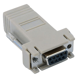
You can use a N0211605 adapter (for MGU) with the following RJ-45 cable:
4 → 4 , 3 → 5 , 6 → 6
(MRV end is standard 568B)
| MRV (568B) | ERS via N0211605 |
|---|---|
| 4 - Blue | 4 - Blue (GND) |
| 3 - White/Green | 5 - White/Blue (TXD) |
| 6 - Green | 6 - Green (RXD) |

N0211605 Adapter