The MG1010 chassis
The Media Gateway 1010 (NTC310AA).
 Front View |
 Rear View |
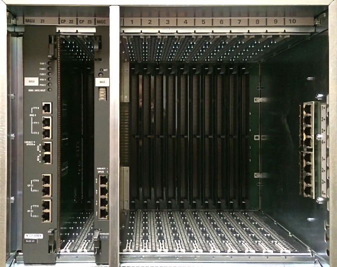
The Media Gateway 1010 (MG1010) is a rack mount Media Gateway chassis that provides a larger amount of card slots than a MG1000E with Media Gateway Expander. The CS1000E Call Server can connect to and control a maximum of 50 MG1010s. Each MG1010 provides a dedicated Gateway Controller slot, two dedicated Server card slots, and ten slots for IPE cards.
Slots from left to right:
- 1 Media Gateway Utility (MGU) card slot: 21
- 2 server card (CPDC/CPPM) slots: 22/23
- 1 Media Gateway Controller (MGC) slot: 0
- 10 Peripheral Equipment (IPE) slots: 1 to 10
- Slots 22 & 23 are dedicated for Server cards (CPDC/CPPM), with only power and MGU connections.
- Slot 0 is reserved for the Media Gateway Controller (MGC). Server cards cannot be placed in slot 0.
Server cards can also be placed in IPE slots 1 through 10, supporting a total of 12 in the chassis.
Server cards in slots 1-10 require the NTAK19EC - 2 port SDI cable for serial TTY connections.
Note: MG1010 Peripheral Equipment (IPE) slots are numbered 1 to 10, whereas NT8D37 IPE Module slots are numbered 0 to 15.
The MGU utility card provides visual monitoring of PSU, fan, and temperature status. It also provides access to the three serial ports of the MGC in slot 0, and to the two serial ports of each Server card in slots 22 and 23 (via RJ45's). It supports all international requirements for ringing and message waiting voltages, set by DIP Switches on the PCB. The MGU is hot-pluggable, thus you can remove/connect it with the system turned on, although analog sets will not ring (preventing incoming analog calls) while it's removed.
The MG1010 was intended for Rls 6 and above, however they are backwards compatible to Rls 5. The MGC loadware patch FPGA16 corrects the fans running at full speed with Rls 5 & 5.5. If you require this patch, it can be installed via Element Manager.
Note: the fans will run at full speed until the MGC card registers, or when a MGU fault condition exists.
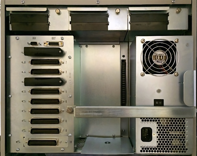
Rear panel:
- Three field replaceable, hot swappable variable speed blower units.
- Hot swappable (optional redundant), auto-switching power supplies (NTC312AAE6).
- Ten RJ21 Amphenol (male) 50 pin 25 pair MDF connectors (for the IPE slots).
- One DECT connector
- One AUX connector
Note: in order to fit a second (redundant) power supply, the safety plate (covering up the PSU connector) needs to be removed. Losen the two phillips screws through the holes, and push or slide the cover up to remove it. Re-tighten the screws.
An air filter (NTC315AAE6) is mounted under the card cage from the rear. A regular monthly inspection of this filter should be performed to avoid any air flow issues which may cause overheating.
MGU TTY Connections:
Serial TTY ports (RJ45's) from top to bottom (click image to zoom):

|
|
The NTC325AAE6 serial cable kit includes one N0211606 RJ45 to DB25
(male) adapter, which is intended to connect the MG1010 to a DCE device
such as a modem, and two N0211605 RJ45 to DB9 (female) adapters which
have an integrated null modem and are intended to connect the MG1010 to
DTE devices such as a terminal or PC serial port.
Connect: MGU Serial Port → Straight Ethernet Cable → MG1010 DB9/RJ45 Adapter → PC COM port for serial TTY access. |
MGU Pin definitions and connection details
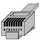
| RJ45 Pin # |
Colour (T-568B) |
MGC SDI 1 |
MCG SDI 2/3 |
CP 1/2 SDI 1/2 |
N0211606 DB25 modem (DCE) |
Standard DB9 serial port pin definition |
Description (signal direction is from DTE perspective) |
|---|---|---|---|---|---|---|---|
| Signal | Signal | Signal | DB25 Pin # | DB9 Pin # | |||
| 1 |  |
nc | nc | DSR | 6 | 6 | Data Set Ready ← |
| 2 |  |
DCD | nc | DCD | 8 | 1 | Data Carrier Detect ← |
| 3 |  |
12v | nc | DTR | 20 | 4 | Data Terminal Ready → |
| 4 |  |
GND | GND | GND | 7 | 5 | Ground |
| 5 |  |
RXD | RXD | RXD | 3 | 2 | Recieved Data ← |
| 6 |  |
TXD | TXD | TXD | 2 | 3 | Transmitted Data → |
| 7 |  |
nc | nc | CTS | 5 | 8 | Clear To Send ← |
| 8 |  |
12v | nc | RTS | 4 | 7 | Request To Send → |
N0211605 DB9 Null Modem adapter
Use this pinout to connect between an MGU TTY port and a PC serial (or usb adapter) port.

N0211605 Adapter
| MGU RJ45 | Colour | Signal | DP9 Female |
|---|---|---|---|
| 1 & 2 & 3 | nc | 1 & 4 & 6 | |
| 4 | |
GND | 5 |
| 5 | |
← RXD | 3 |
| 6 | |
→ TXD | 2 |
| 7 & 8 | nc | 7 & 8 |
RJ45 end: 1 & 2 & 3 are looped, 7 & 8 are looped (required!).
DB-9 end: 1 & 4 & 6 are looped, 7 & 8 are looped (not required if handshake=none on PC).
(nc: not connected)
MGU TTY to MRV pinout:
Use the following pinout for serial communications between an MRV and the MGU serial ports.
This configuration works for either CPDC, CPPM, or MGC cards.
MGU TTY to MRV: 1-5 , 2-2 , 3-7 , 4-4 , 5-3 , 6-6 , 7-8, and 8-1 .
| MGU TTY | |||||||
|---|---|---|---|---|---|---|---|
| 1 | 2 | 3 | 4 | 5 | 6 | 7 | 8 |
 |
 |
 |
 |
 |
 |
 |
 |
| MRV Port | |||||||
|---|---|---|---|---|---|---|---|
| 1 | 2 | 3 | 4 | 5 | 6 | 7 | 8 |
|
|
|
|
|
|
|
|
The MGU TTY end is standard 568B. The MRV Port end is custom.
ADAN TTY TYPE: MGC, ports 0, 1, 2