CallPilot 600r Installation Notes
Identify the hardware!
You will need to find:
- 600r 1U rack mount server, and software
- Security button/dongle in a blue USB stick
- MGATE card (NTRB18DA) for the CS1000
- Server ELAN and DS30 (MGATE) hookups
Hooking up:

| Label | Description | Label | Description |
|---|---|---|---|
| A | Secuity device in USB port 0 | G | Ground studs (not used) |
| B | PS/2 Mouse | H | ELAN (labelled 2) |
| C | SCSI tape drive chain | I | CLAN (labelled 1) (not used) |
| D | DS30 to MGate (RJ-45) | J | Monitor |
| E | PSU | K | COM1 serial |
| F | AC power input | L | PS/2 keyboard |

Fit a VHDCI SCSI terminator to the SCSI connector (C).
Forgetting this will prevent CallPilot from booting.


CS1000 MGate card:
Install the MGate card in the Media Gateway. Consider how many DSP's the shelf has (on the MGC card) to minimise network blocking, add more DSP's if necessary. You can install MGate cards in any IPE slot, though multiple MGate cards (for the same CallPilot) must reside together in the same Media Gateway shelf as they need to share the same clock reference. MGate cards are hot-swappable.
Connect the DS30X RJ-45 cable between the MGate and the MPB96 board in the server. One MGate/DS30X supports upto 32 channels, so supporting 96 channels will require 3 MGate cards. Your keycode will tell you how many channels you require.
The server MPB96 DS30 ports (item 'D' above) are numbered and cabled from left to right (1 to 3) as shown below:

DS30 CAT-5E RJ-45 Pin-out:
| RJ-45 pin | MPB96 function | MGate function |
|---|---|---|
| 1 | DS30 RXP | DS30 TXP |
| 2 | DS30 RXN | DS30 TXN |
| 3 | DS30 TXP | DS30 RXP |
| 4 | - Unused | - Unused |
| 5 | - Unused | - Unused |
| 6 | DS30 TXN | DS30 RXN |
| 7 | - Unused | - Unused |
| 8 | - Unused | - Unused |
| Shield | Frame GND | Frame GND |
The CAT-5E cable connection must be:
- End-to-end, non-routable (signaling only)
- Maximum cable distance of 600 meters (1968 feet)
- A maximum of two (2) Female-to-Female couplers should be used
- Bridge points and punch downs will result in signal loss and are therefore not supported
Note: A DS30X RJ-45 cable is used for an NTRB18CA MGate card, but a standard CAT5E Ethernet patch cable can be used with the newer NTRB18DA MGate card.
MGate Card Link Indications:
When the DS30X RJ-45 / CAT-5E cable is connected to the MGate (NTRB18DA) RJ45 faceplate connector, the Green LED should light, and the Yellow LED extinguish.
ON = Good DS30 signal from far end
OFF = No DS30 signal from far end
Yellow LED:
OFF = Normal
ON (blink) = Frame slip event
ON (steady) = No DS30 signal
 DS30 LED's")
CS1000 programming
ACD programming:
Set up an ACD agent queue for CallPilot. This queue holds all the agents that correspond to DS0 channels on the CallPilot server.LD 23
| Prompt | Response | Description |
|---|---|---|
| REQ | NEW | Add new data |
| TYPE | ACD | Indicates this is an ACD queue. |
| CUST | xx | Customer number (0-99) |
| ACDN | yyyy | This is the ACD DN for CallPilot. |
| MWC | NO | Message Waiting Center |
| MAXP | zzzz | Maximum number of agents. MAXP must be equal to or greater than the total number of multimedia channels installed on your system. |
| IVR | YES | Interactive Voice Response queue |
| CALP | POS or TER | Called Party DN POS - Sends the POSID+DNIS in the called Party DN field in the PCI message TER - Sends the terminating DN in the called Party DN field in the PCI message |
| ALOG | YES | Provide automatic logon for ACD agents. |
| <Enter> | Press Enter until you reach the REQ prompt. | |
| REQ | **** | Exits the overlay. |
Configuring ACD agents:
Define channels as ACD agents on M2008 digital sets. All agents are added to the ACD queue you just configured. Each agent must have the VCE and MMA class of service. To get the VCE class of service on the upper 16 units (15 to 31), you must first specify the FLXA class of service. Each agent must be provisioned with the following feature keys: ACD, SCN, NRD, MSB, TRN, and AO3.
Terminal numbers:
- Integrated (201i or 202i): ACD agents use TNs associated with the slot location of the 201i or 202i server card.
- Tower/rackmount servers: ACD agents use TNs associated with the slot location of the MGate card (NTRB18).
Position IDs:
You also need a Position ID for each agent. The server uses the position ID to inform the CS 1000 system to which agent an incoming call should be routed. Use sequential numbers to avoid confusion!
Configure agents in LD 11:
| Prompt | Response | Description |
|---|---|---|
| REQ | NEW | Add new data |
| TYPE | 2008 | ARIES digital set with 8 programmable keys. |
| TN | l s c u | Terminal number of the MGate card, or the 201i or 202i server. |
| CUST | xx | Customer number (0-99) |
| CLS | WTA UNR VCE MMA (units 0-15) FLXA UNR VCE WTA MMA | Voice terminal, Multimedia Agent, Flexible voice/data allowed for units 0-15.
|
| key | 0 acd xxxx 0 yyyy | Where xxxx is the DN of the CallPilot agent queue, and yyyy is the agent Position ID. |
| key | 1 scn zzzz | where zzzz is the single-call nonringing DN used to make outbound calls. |
| key | 2 msb | Make Set Busy |
| key | 3 nrd | Not Ready |
| key | 4 trn | Transfer |
| key | 5 ao3 | Three-Party Conference |
| AST | 0 1 (IVR & Access Agents only) | If you are enabling the Contact Center Voice Services Support feature, you must define 0 and 1 as the AST key0 and key1 values. If you are not enabling the Contact Center Voice Services Support feature, then press Enter to skip this prompt. |
| <Enter> | Press Enter until you reach the REQ prompt. | |
| REQ | **** | Exits the overlay. |
Enabling the card slots:
After you have configured the ACD agents, use overlay 32 to ensure that the card slots used by an MGate card (NTRB18CA or NTRB18DA) or 201i or 202i server are enabled.
- Load overlay 32.
- Type STAT n ↵, where n is the card slot used by an MGate card or the 201i/202i server.
- Type ENLC n ↵, where n is the card slot used by an MGate card or the 201i/202i server.
- To verify that the card slot & ACD agents are enabled, type STAT n ↵, where n is the card slot (MGate card or 201i / 202i).
- Repeat this procedure for all other card slots used by an MGate card or the 201i or 202i server.
Defining the default ACD DN:
Before you configure the CDN queue, define the default ACD DN that needs to be referenced in the CDN. During normal operation, the CDN is in control mode, and callers are queued to be routed and then answered by CallPilot services. Under error conditions (for example, if the AML link is down), the CDN operates in default mode and calls are routed to the default ACD DN defined for the CDN. This section describes how to set up the default ACD DN so that these calls are handled by the attendant.
For the attendant to process incoming calls to CallPilot when the CDN is in default mode, define a dummy ACD DN and set it to night call forward to the attendant.
LD 23:
| Prompt | Response | Description |
|---|---|---|
| REQ | NEW | Add new data |
| TYPE | ACD | Indicates this is an ACD queue. |
| CUST | xx | Customer number (0-99) |
| ACDN | yyyy | The ACD DN. Enter this DN as the DFDN in the CDN configuration. |
| MWC | NO | Message Waiting Center. Set to NO |
| MAXP | 1 | This indicates that there are no agents in this queue and it is, therefore, a dummy queue. |
| NCFW | 0 | Night call forward to the attendant. |
| <Enter> | Press Enter until you reach the REQ prompt. | |
| REQ | **** | Exits the overlay. |
Configuring CDN queues for messaging services:
Configure a primary CDN for Voice Messaging. This becomes the main CDN queue.
Note: Nortel strongly recommends that you use either a phantom DN or a dummy ACD DN for all other messaging services.
LD 23:
| Prompt | Response | Description |
|---|---|---|
| REQ | NEW | Add new data |
| TYPE | CDN | Control DN queue |
| CUST | xx | Customer number (0-99) |
| CDN | yyyy | The Control DN of the queue. This number must be entered as the SDN for the messaging service in the SDN Table. |
| DFDN | zzzz | The default ACD DN. Calls to the CDN are directed to this ACD DN if the link or CallPilot goes down. Nortel recommends that this is not defined as the ACD DN of the CallPilot ACD queue. |
| VSID | <Enter> | Press Enter so that the ID is dynamically assigned to the CDN when the ELAN subnet link is established. |
| <Enter> | Press Enter until you reach the REQ prompt. | |
| REQ | **** | Exits the overlay. |
Configuring phantom DNs:
Found elsewhere on this site....
Configuring the CallPilot server software
To run the Setup Wizard:
|
|
After you type the user ID and password, the CallPilot Setup Wizard welcome screen appears.
- Read the information displayed on the screen and click Next.
- If there are Service Updates (SUs) or PEPs available, you can choose to install them now. Select Yes or No and click Next.
If you choose Yes, install SU/PEPs, the Installing SU/PEP screen appears.- Install all the required SUs and PEPs.
- Restart CallPilot (if required)
- the Setup Wizzard lauches again...
- View the items on the validity check and click Next.
- When the system asks you if you have data to restore, select No.
- Click Next to complete the Setup Wizard. The Finished screen appears.
- Read the information displayed on the Finished screen and click Finish.
Logging on to the CallPilot server with CallPilot Manager:
Launch the web browser on your PC or on the CallPilot server (must both be connected to the ELAN). Enter CallPilots IP address in the URL window.
When the connection is established, the CallPilot Manager - Login page appears.
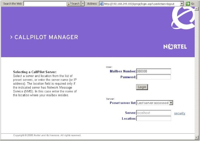
Note:
The URL automatically appears as: http://<host name or IP address>/cpmgr/login.asp
On the CallPilot server, the URL is: http://localhost/cpmgr/login.asp
To log on to the CallPilot server:
|
|
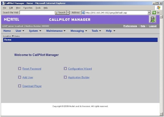
Note: Logging on for the first time forces you to change the password using numeric characters.
Checking that CallPilot is ready to accept calls:
The system-ready indicators appear only if the Configuration Wizard has previously been run on the server. The CallPilot server is not ready to accept calls if the Configuration Wizard has not been run.
Can you ping the callserver from Callpilot?
To be continued......