UDT E1/T1 - Universal Digital Trunk card

Hardware:
- NTDW79 - E1/T1 Universal Digital Trunk card;
- NTDW12 - Clock Controller daughter board.
The UDT E1/T1 replaces the NTAK79, NTAK09, NTAK10, NTBK50, and NTRB21. It is backwards compatible, and software transparent. DDCH/DCHI functionality is implemented onboard. It can be used in the following modes:
- DTI 1.5/DTI 2.0
- PRI 1.5/PRI 2.0
- DPNSS/DASS2
- B-channel
A Clock Controller (CC) is optional, only one CC daughter board is required per Media Gateway.
Put the UDT card in the first free slot nearest the MGC, eg, deploy PRI cards from left to right.
Configuring
There are 3 steps to configuration:

- E1 or T1 mode - set by DIP switch S1 on the card: OFF = T1 / ON = E1.
Seat card. The EN/DIS LED remains red until the card is enabled in LD 60. - Configuration via CLI, with the command:
udtadmin/E1T1Settings
This is required for any non default mode setup. Always check a used card.
Default modes: E1 - PRI2, CRC4: No
T1 - PRI, ESF, B8ZS, FDL, LBO: 0..133 ftNon-default modes: DTI2, DTI, DDCS, BCH, CRC4: Yes - Call Server programing of route and trunks.
Do not configure UDT E1/T1 as TMDI card! It's an MSDL.Call Server programing examples: E1 PRI Example, T1 DTI Example
For more information, refer to: ISDN Primary Rate Interface Installation and Commissioning NN43001-301
Configuration via CLI:
| DB9 | ➤ | RJ45 |
|---|---|---|
| 2 TXD | - | 6 RXD |
| 3 RXD | - | 3 TXD |
| 5 GND | - | 5 GND |
Access to the CLI is via the serial MAINT port (9-pin D) on the cards face plate.
Only pins 2 (TXD), 3 (RXD) and 5 (GND) are connected. You may need a Null-Modem.
The communication settings are: 9600/8n1, no flow control.
If you're connecting the UDT card to an MRV, use the pin-out shown right:
Or use 2x MG1010 DB9 to RJ45 Adapters (N0211605) with an ethernet patch cable:
UDT Card → MG1010 DB9/RJ45 Adapter → Straight Ethernet Cable → MG1010 DB9/RJ45 Adapter → PC COM port
When the serial cable is correctly hooked up, hitting enter will return a UDT [1 /] prompt.

N0211605 Adapter
for serial console
The available directories are:
| smaint | - System Maintenance directory |
| udtadmin | - UDT Administration directory |
| udtmaint | - UDT Maintenance directory |
You can type help, or ? in each directory for a list of available commands.
CLI config example:
In the following example, we will enable CRC4 on an E1 PRI2 circuit:
We need to go to the udtadmin directory to change the E1T1Settings:
- At the UDT prompt, enter the command:
udtadmin/E1T1Settings - At the prompt Modify, Save, Cancel: enter
mto modify - At the prompt CRC4 (No, 1-Yes ): enter
1for yes - At the prompt Modify, Save, Cancel: enter
sto save - The UDT card will re-boot and load the new settings.
Note: CRC4 must be enabled on both the UDT card, and in LD 73: at the MFF prompt, enter CRC (default: AFF).
TTY Output:
UDT [1 /]  udtadmin/E1T1Settings               enter settings
E1/T1 Settings:
Protocol: E1                                   ← Card set to E1 mode
Usage:PRI2
CRC4: No
Modify, Save, Cancel: m                        modify settings

Protocol E1

Usage (PRI2, 1-BCH, 2-DTI2, 4-DDCS ):          hit enter to accept default PRI2

CRC4 (No, 1-Yes ):1                            enter 1 to enable CRC
New E1/T1 Settings:
Protocol: E1
Usage: PRI2
CRC4: Yes
Modify, Save, Cancel: s                        save changes
With the DIP switch set to T1, the menu is different, set below is: DTI, ESF, B8ZS:
UDT [1 /] udtadmin/E1T1Settings
E1/T1 Settings:
Protocol: T1                                   ← Card set to T1 mode
Usage:DTI
Frame Mode: ESF
Line Code: B8ZS
Yellow Alarm: FDL
LBO: 0..133ft
Modify, Save, Cancel: c
UDT [2 /]
Note: Always check the DIP switch position and E1T1Settings before deploying a new or used card.
E1/T1 Connectiion:
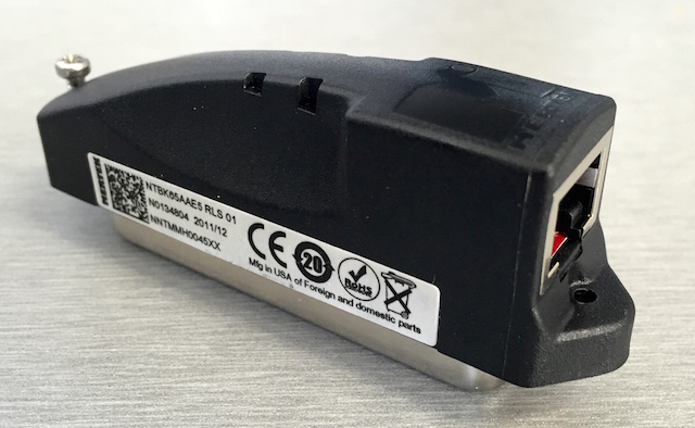
Media Gateways (and Option 11's) can use a NTBK65 adapter, or a direct MDF connection from the the UDT card slot RJ21. See Connecting E1/T1's for wiring details. The RJ-48/RJ-45 uses pairs 1 & 2 (568B: blue and orange) for TX and RX.
If you can't find an NTBK65 UDT RJ48C breakout adaptor (right), use pairs 23 (TX) and 24 (RX) on the MDF. If the circuit doesn't go green, try swapping the TX/RX pairs.
Note: An RJ-48 is a keyed RJ-45. An RJ-45 connector will fit an RJ-48 jack, but the key on an RJ-48 connector will prevent it from plugging into an RJ-45 jack.
UDT card firmware upgrade:
It may be necessary to patch UDT cards following a loadware upgrade. Before doing so, disable the MSDL in LD96 and the loop in LD60. Use the following Load 143 UDT firmware upgrade commands:
UPGUDT STAT- Query current UDT card firmware upgrade status.UPGUDT l s c- Perform UDT card firmware upgrade on [supl shelf card]UPGUDT ABORT- Abort UDT card firmware upgrade.
To check the firmware version in LD 60: VER <UDT Digital Loop Number>.
NOTE: Make sure that the MGCs are fully registered to the Security Domain before attempting a loadware upgrade. If necessary, regenerate the Secure FTP token from UCM and then start the upgrade again. If the upgrade fails, it may be necessary to:
- Cold start both CS cores while split.
- Unregister and register both CS to the Security Domain.
- Confirm using Regenerate Now button on Secure FTP page within UCM.
- Join the cores.
Further details on patching, see: Load Patch procedure.