Connecting E1 / T1's
A 2 pair connection (TX/RX) between the service providers CSU/DSU (Channel Service Unit/Data Service Unit) and the customers PBX. It can use a number of different connection methods depending upon the service, provider, equipment, and location:
| ⇠ Provider Equipment | ¦ | Customer Equipment ⇢ | ||
| CSU/DSU DB-9 / DB-15 / RJ-45 | → | MDF (optional) | → | PBX DB-9 / RJ-45 / Amphenol |
A TX pair will generally connect to a RX pair, but be prepared to experiment a little (and/or swap/crossover the pairs).
- A Red "Near End Alarm" (NEA) indicates a local cabling problem, with the RX (or both) pairs open.
- A Yellow "Far End Alarm" (FEA) indicates the local TX pair is open (a yellow alarm is "received").
CSU/DSU Pinouts:
A circuit can be presented on a DB-9 (E1) , DB-15 (T1), or RJ48/RJ45. The following table shows the pinouts for each:
| DB-9 (E1) (NT8D7217E6) | DB-15 (T1) | CSU/DSU * (RJ48/RJ45) | T-568B Pairs |
|---|---|---|---|
| 2 - Black/TX | 1 - White/TX | 1 - TX (R1) |  |
| 3 - Red/TX | 9 - Black/TX (could be 8) | 2 - TX (T1) |  |
| 6 - Black/RX | 3 - Red/RX | 4 - RX (R) |  |
| 7 - White/RX | 11 - Black/RX (or Yellow) | 5 - RX (T) |  |
 Pinout") |  Pinout") |  Pinout") |  |
* CSU/DSU = Channel Service Unit/Data Service Unit, eg, the PTT modem.
Note: When using RJ-45's, remember it isn't ethernet! The active pairs in a T1/E1 network are pins 1 & 2 and pins 4 & 5, not 1 & 2 and 3 & 6. Ethernet accessories (eg, patch panels) may either not work or cause problems. A single direct CAT5/6 cable is always preferred.
PBX hookup:
Loopback: pins 1 to 4, and 2 to 5
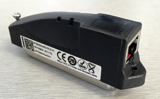
Media Gateways  (and Option 11's) can use an NTBK04 cable, NTBK65 adapter, or a direct MDF connection.
If you can't find an NTBK65 UDT RJ48C breakout adaptor (right), use pairs 23 (TX) and 24 (RX) on the MDF. If the circuit doesn't go green, just swap the TX/RX pairs.
Note: An RJ-48 is a keyed RJ-45. An RJ-45 connector will fit an RJ-48 jack, but the key on an RJ-48 connector will prevent it from plugging into an RJ-45 jack.
A standard RJ-45 ethernet cable (568B) works, but note the active pairs are orange and blue, not orange/green. Be prepared to swap these, to switch the TX / RX pairs.
The following table shows the NTBK65 adaptor signal pin out:
| Amphenol | RJ48C | Signal | (T-568B) |
|---|---|---|---|
| 24 | 1 | RX Ring | |
| 49 | 2 | RX Tip | |
| 3 | n/c | ||
| 23 | 4 | TX Ring | |
| 48 | 5 | TX Tip | |
| 6 | n/c | ||
| 7 | n/c | ||
| 8 | n/c |
MDF Termination:
The NTBK65 is a replacement to the NTBK04 cable assembly. If neither are available, make the termination directly on the MDF block associated with the card slot using the following pinout. If the circuit doesn't go green, swap the TX/RX pairs:
| Cable Patching |
Violet/Green |  | Transmit (TX) - to network | TIP 0 | MDF/BIX Pair 23 |
|---|---|---|---|---|---|
| Green/Violet | RING 0 | ||||
| Violet/Brown |  | Receive (RX) - from network | TIP 1 | MDF/BIX Pair 24 | |
| Brown/Violet | RING 1 | ||||
| Slate/Violet | Frame Ground | FGND | Not Used |
RJ45 to DB-9F (E1) Adapter:
Large systems (51C/61C/81C) use a DB-9 (E1), or DB-15 (T1) connector, located at the rear of a network shelf  .
.
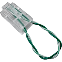
The picture also shows an improvised RJ45 loopback adapter used for testing (blue and orange pairs looped)!
Use the following adapter configuration with an E1, DB-9 end on the PBX (to NTCK45AA on J5).
You may need to reverse the TX / RX pairs - or swap orange & blue with T-568B (568A or 568B).
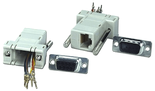
Note: Most RJ45 to DB-9F Adapters use this colour
scheme, but yours may not! Always check it first!
| RJ-45 | Colour | DB-9 |
|---|---|---|
| 1 | Blue | 2 |
| 2 | Orange | 3 |
| 3 | Black | |
| 4 | Red | 6 |
| 5 | Green | 7 |
| 6 | Yellow | |
| 7 | Brown | |
| 8 | White |
RJ45 to DB-15F (T1) Adapter:
Use the following adapter configuration with a T1, DB-15 end on the PBX.
You may need to reverse the TX / RX pairs - or swap orange & blue with T-568B (568A or 568B).
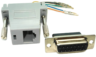
Note: Most RJ45 to DB-15F Adapters use this colour
scheme, but yours may not! Always check it first!
| RJ-45 | Colour | DB-15 |
|---|---|---|
| 1 | Blue | 1 |
| 2 | Orange | 9 |
| 3 | Black | |
| 4 | Red | 3 |
| 5 | Green | 11 |
| 6 | Yellow | |
| 7 | Brown | |
| 8 | White |
Loopback Adaptors:


- DB-9 (E1) - Loop pin 2 to pin 6, and pin 3 to pin 7
- DB-15 (T1) - Loop pin 1 to pin 3, and pin 9 to pin 11
- BIX frame - Loop pairs 23 & 24 (pins 45-47 & 46-48)
With a 568B cable, jumper the Orange to Blue pair.
Note the improvised loopback adapter in this picture!
Remember, the D channel will not establish on a loop test.
- RJ45 (DSU) - Loop pin 1 to pin 4, and pin 2 to pin 5
Note: An RJ45 connector will fit an RJ48 jack, but the key on an
RJ48 connector will prevent it from plugging into an RJ45 jack.
G.703 Balun:

An E1 maybe presented on two coaxial connectors (eg, BNC's), one each for TX and RX. A G.703 Balun is a bi-directional passive device (transformer) that converts unbalanced (75 ohm, BNC) to balanced (120 ohm, RJ45) signals. The RJ45 side uses the standard pairs: 1 & 2, and 4 & 5. If a circuit is presented on coaxial connectors, always use a balun with a matching impedance, eg: 75 to 120 ohm.
| BNC | RJ45 | (T-568B) |
|---|---|---|
| TX (out) | 1 - Transmit (R1) | |
| 2 - Transmit (T1) | | |
| RX (in) | 4 - Receive (R) | |
| 5 - Receive (T) | |
Media Converters:

DS1 - T1/E1 converters must be used in pairs, one on each end of the fiber link.
Refer to the user-guide (NID) to set the DIP switches (T1 or E1 mode) as required.
The two RJ-45 active pairs in a T1/E1 network are pins 1 & 2 and pins 4 & 5. Use only dedicated wire pairs (such as blue/white & white/blue, orange/white & white/orange) for the active pins. Category 3 or better shielded twisted-pair (STP) or unshielded twisted-pair (UTP) can be used.
The front panel CL – FL switch selects a loopback test mode:
- FL - Loopback on Fiber port
- CL - Loopback on Copper port
For normal operation, the CL – FL switch must be in the center position.
- Signal Detect Fiber/Copper LED's:
- Link is up
- AIS (Alarm Indication Signal)
- Loopback mode