M1 Power Description
The Meridian PBX should have a dedicated circuit breaker on an Electric Service Panel located in the Telephone Equipment room. Do not use ground fault circuit interrupter (GFCI) breakers for any Meridian 1 Telephone Switch. To calculate the total power consumption of your Meridian, add all the watts consumed for each component. Power consumption will vary depending on traffic load. The following table assumes a busy percentage of 25% for analog and digital lines, and 75% for trunks (Watts=Volts x Amps).
| Module | Power (watts) | Heat BTU/hr |
|---|---|---|
| NT8D35 Network Module | 270 | 820 |
| NT8D36 InterGroup Module | 0 | 0 |
| NT8D37 IPE Module | 460 | 1160 |
| NT9D11 Core/Network Module | 260 | 1230 |
| Meridian Mail | 240 | 820 |
| Pedestal (with blower unit) | 50 | 170 |
| Circuit Card | Power (watts) | Heat BTU/hr |
|---|---|---|
| NT8D01 Controller Card-2 or 4 | 26 | 65 |
| NT8D02 Digital Line Card | 20 | 50 |
| NT8D03 / NT8D09 Analog Line Card | 16 | 40 |
| NT8D14 Universal Trunk | 28 | 70 |
| NT8D15 E&M Trunk Card | 26 | 65 |
| NT8D16 Digitone Receiver Card | 6 | 15 |
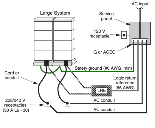
AC powered: No power components external to the Meridian 1 Columns are required-- 208-240 VAC from the Power Distribution Unit (PDU) in the pedestal is distributed to the module power supplies for AC to DC conversion. AC modules have large circuit breakers to the left of the module power supplies which are not present with DC powered modules.
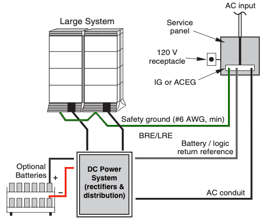
DC powered: Each Meridian 1 Switch can have up to six 25-amp rectifiers in parallel. The rectifiers -48VDC output is distributed by the pedestal to the module power supplies. A bank of sealed lead acid batteries provides 8-20 hours of reserve power. There is no physical switch involved when the Meridian PBX goes from rectifier to battery-System power floats in parallel with the battery voltage. The acceptable power range for an Option 51-81C is 42 VDC-56.5VDC (11C: 43-54VDC). If the output of the MFA-150 rectifiers drops below 43.5VDC, a relay disconnects them from the batteries and Distribution Panel. Prior to removing DC power supplies, turn off breakers in the pedestal.
Optional batteries: As the PBX, rectifiers and batteries are connected in parallel, for maintenance, you can safely set the 'Battery Isolation Breaker' to OFF and the PBX will continue to run from the MFA150/MPR25 rectifier stack. Phone systems are positive ground, which means the battery positive lead is strapped to ground. Nortel uses BLACK for POSITIVE and RED for NEGATIVE.
Note: As a safety precaution, all AC service panels should be located in an area that is easily accessible at all times. Each circuit breaker should be clearly marked to identify the system component or components it services.
Module power supplies: A steadily lit green LED on the Equipment Module power supply indicates that it is operating normally.
Ringing Generator: Only required for Analog phones. A NT6D42 ringing generator will ring up to 48 bells simultaneously. However the number of ringing lines is reduced if Distinctive Ringing is used which requires 2.5 times as much ringing time as standard ringing.
Power Fail Transfer Unit: Each PFTU has eight PFTU circuits which connect analog trunks directly to phones in the event of a switch failure. Normally transfer is made only during a 48vdc power failure. If wired, transfer can occur if call processing is halted, or if a Sysload occurs. Also, if wired, a switch under a 2250 console, can invoke a transfer.
Source: Nortel Training Documentation.

