Replacing the Battery Bank
A DC powered PBX requires a nominal -54 volt supply typically from a large float charged battery and constant voltage charger, all connected in parallel. The battery is able to sustain the PBX in case of a power failure, and is usually comprised of 24 x 2.25 volt cells strapped in series. Sometimes the cells are strapped as 4 x 13.5v, where each 13.5v pack is made from 6 x 2.25 volt cells.
- Unigy 2 cells are rated at 2.25 VPC (volts per cell). 24 cells in series = 54 VDC nominal float voltage.
- Absolyte GP cells are rated at 2.23 to 2.27 VPC, eg 24 cells = 54 VDC nominal system float voltage.
If the battery bank sits on float for 15 years, and is rarely or never exercised, it will fail you in its moment of need.
If you see signs of ware, such as bulging, cracked, or leaking cells, you should replace it, or find an alternate solution.
Obviously, when assessing the suitabiility of replacement cells, look very carefully at the manufacturers specifications.
- Always select deep-cycle sealed (non-venting) lead acid gel type replacement batteries.
- The bank voltage must not exceed the specified maximum DC input voltage (56.5 volts).
Replacing the Batteries:
You can replace the batteries with the PBX 'online', without service interruption.
1 Set the 'Battery Isolation Breaker' to OFF - the PBX will continue to run from the MFA150/MPR25 stack.
The design may vary, but it will look something like below. ON = Battery Connected, OFF = Battery Isolated.

DO NOT WORK ON CONNECTIONS WITH BATTERY CONNECTED TO CHARGER OR LOAD.
2 Note the positions of the battery plus/minus terminals and charger/load cable routing. Take a photo for reference!
Both cables may be black, or the positive cable BLACK and the negative cable RED. Phone systems are positive ground.
3 Remove the battery charger/load cables (positive/negative), and tape them to prevent short circuits.
With the 'Battery Isolation Breaker' OFF, there should be no voltage potential on these cables when disconnected.
4 Replace the battery bank with your new cells. Batteries are extremely HEAVY, so you will need (a lot of) help!
Position the new bank, making sure that the cables will reach the terminals. You will not want to move it later!
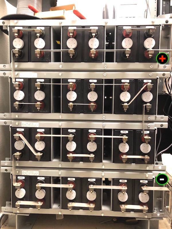
 Old battery stack, plus terminal at the top |
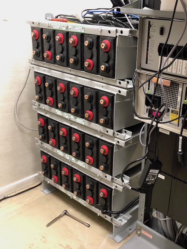
 Replacement battery stack in position |
5 Strap the new cells so that the final plus and minus terminals are in the correct positions, using the hardware provided.
Apply a thin film of NO-OX-ID “A” grease to each connection surface, and torque to 100 inch pounds (11 Newton Meters).
6 Check the voltage and polarity with a meter and be sure its correct (!) before carefully connecting the charger cables.
Connect battery positive (+) terminal to charger positive (+), and battery negative (-) terminal to charger negative (-).
 |
Pay special attention to polarity! Nortel uses BLACK for POSITIVE and RED for NEGATIVE
Phone systems are positive ground, which means the battery positive lead is strapped to ground. Making a mistake with power can make for a very bad day! Always check, and double check your work. |
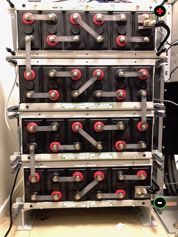
 After connecting, plus terminal at the top |
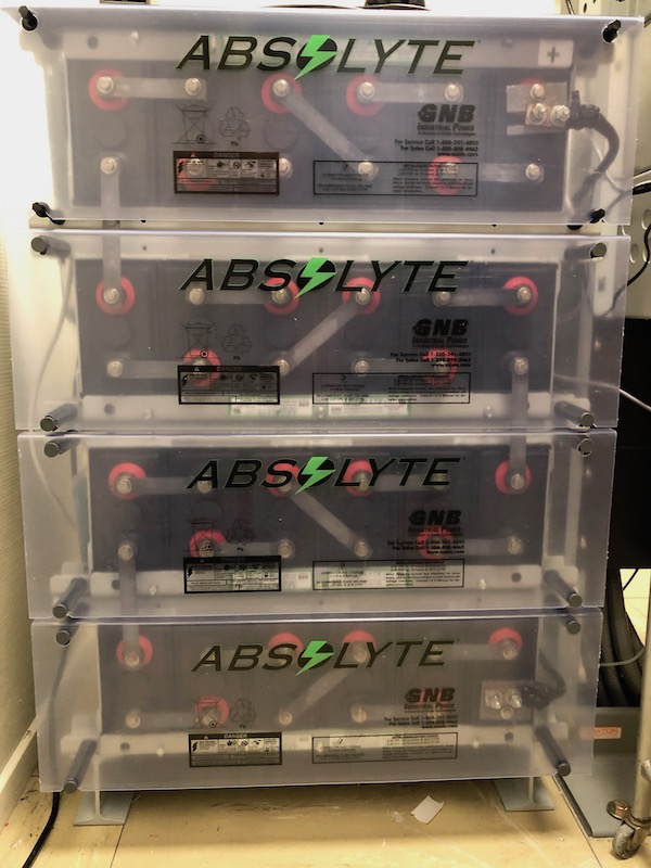
 And with the covers in place |
7 Set the 'Battery Isolation Breaker' back to ON, putting the new battery bank online.
The MFA150/MPR25 will indicate a temporary increase in current flow as the cells receive the initial charge.
8 Check the MFA150 voltage and MPR25 current readings. The battery is charged when the current stabilizes.
Make sure that the float voltage is correct, adjust chargers measured at the battery terminals if necessary.