Equipment Modules

Universal Equipment Modules (UEM) are the M1 system building blocks. UEMs are generic metal frames equipped with covers. Each UEM is a self-contained unit with power, a card cage, I/O panels, and cable routing channels.
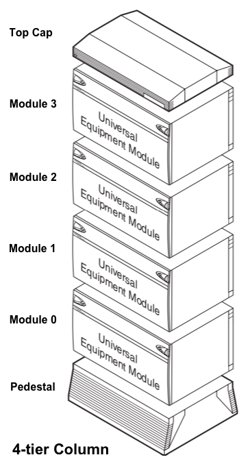
Universal Equipment Modules (UEMs) are stacked in columns up to four modules high. Each column contains a pedestal base, a top cap, and up to four modules. Within a column, the levels are referred to as tiers. The UEMs are numbered 0 to 3 from the bottom up. Power and data cables connect between modules.
Core/Network Module (Options 51C-81C), NT5D21 (release 21): If a CP card with a Pentium II/III processor is used, the existing NT5D2101 Core/Network cage must be replaced by the new Call Processor/Network cage (NTHU22DC). The Option 51C has only one Core/Net module. Options 61C and 81C have a second modules for redundancy. The right half of each module contains the Core with its CP card & hard drive-left half houses Network Group 0.
Network Module (Option 81C only), NT8D35: Is used for network groups 1-4 (1-7 with release 25) in an Option 81C multigroup switch. Provides additional network capacity with additional loops and timeslots to increase the number of terminal connections that can be made. In slots 5-12 of each module there are two loops/slot for a total of 16 loops.
Intelligent Peripheral Equipment Module (IPE) (Options 51C-81C): Contains station cards and analog trunk cards. These cards do not have an enable/disable switch on the front of the card as many Core/Network cards do. They should be software disabled/enabled in load 32 prior to removing or installing. Slots 0 and 1 have high priority and should be used for trunks or other cards where timing is important. Because the Attendant Console by default is given high priority, installing it in slots 0 or 1 will not improve performance.
Fiber IPE Remote (FIRE): 10 km or 6.2mi. using FNET Superloop and FPEC Controller cards. Fiber optic connection to an IPE at a remote site.
Inter Group Module (IGM): One is required for 81C multi-group systems to interconnect network groups if Fiber (FIJI) Rings are not used. It is cabled to both CC cards in the Core/Net module, and to the Inter-group Switch cards in each Network Group. Terminating Plugs must be installed in any unused Network group connectors.
Pedestal and the Power Distribution Unit (PDU): At the base of each column of 1-4 UEMs is a Pedestal. Inside the pedestal is a System Monitor and a PDU with 5 circuit breakers: one for each of the four modules, and a breaker for the fan tray. The system monitor reports the status of power related hardware for its column to the CP card. The CP subsequently sends the system monitor message to the SDI terminals. System monitors are daisy chained together with Jacks 5 and 6. The status of the system monitor is found using Load 37 Stat SM. Note: Clean the filters in the pedestal of all columns regularly.
Top Cap: A Top Cap tops each UEM column. Each is equipped with a thermal sensor, a power alarm light indicator, and air exhaust. The red power alarm will light if any power supply including the ringing generator goes bad. The Meridian 1 can operate in temperatures up to 158 Fahrenheit (70 deg C). If operated above 158 degrees F (70 deg C), the thermal sensor will signal the system monitor in the pedestal and cause it to trip the breakers in the PDU, thereby shutting the entire column down. The recommended environment is 72 degrees Fahrenheit (22 deg C) at 20-55% humidity.
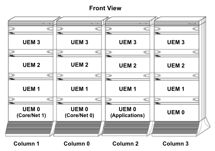
UEM Columns are grouped in rows: A system can have one, or multiple columns attached in rows. Column 0 always contains the “Core/Net 0” module. Column 1 is placed to the left of Column 0 and must contain the “Core/Net 1” module. Column 0 and Column 1 are placed at the far left of the row. Numbering then continues to the right of Core 0 with Column 2, followed by Column 3, etc.

Additional Notes:
- Where the ceiling does not allow four-high columns, the alternate configuration of three-high tiers can be used.
- Vertical routing of the internal signal cables should be done only on the right side of a module (power is on the left side).
- The CPU modules must be on the bottom of a column or one level up for proper cooling and reliability.
- IPE modules can be located separately from the CPU and network bay, the maximum network cable length is 13.5 m (45 ft).
- Core/network modules can also be on top of each other in the first and second tier in multi-group systems.
- Modules that contain application-specific equipment, such as Meridian Mail, can be included in a column.