Power Fail Transfer / Bypass
PBX power-fail-transfer units (PFTU's) will re-direct an analog trunk to an analog
phone (bypassing the PBX), allowing an analog phone to still make and receive trunk calls in
the case of a PBX failure. The units are basically just double pole/double throw relays,
activated by a voltage. Typically, each unit contains eight such relays, allowing it to
re-direct upto eight analog circuits.
Today, with most PBX's having digital trunks, and most users having digital phones, PFTU's are of limited interest. Although, consideration should be given to analog hallway and elevator phones in the event of an emergency or PBX failure.
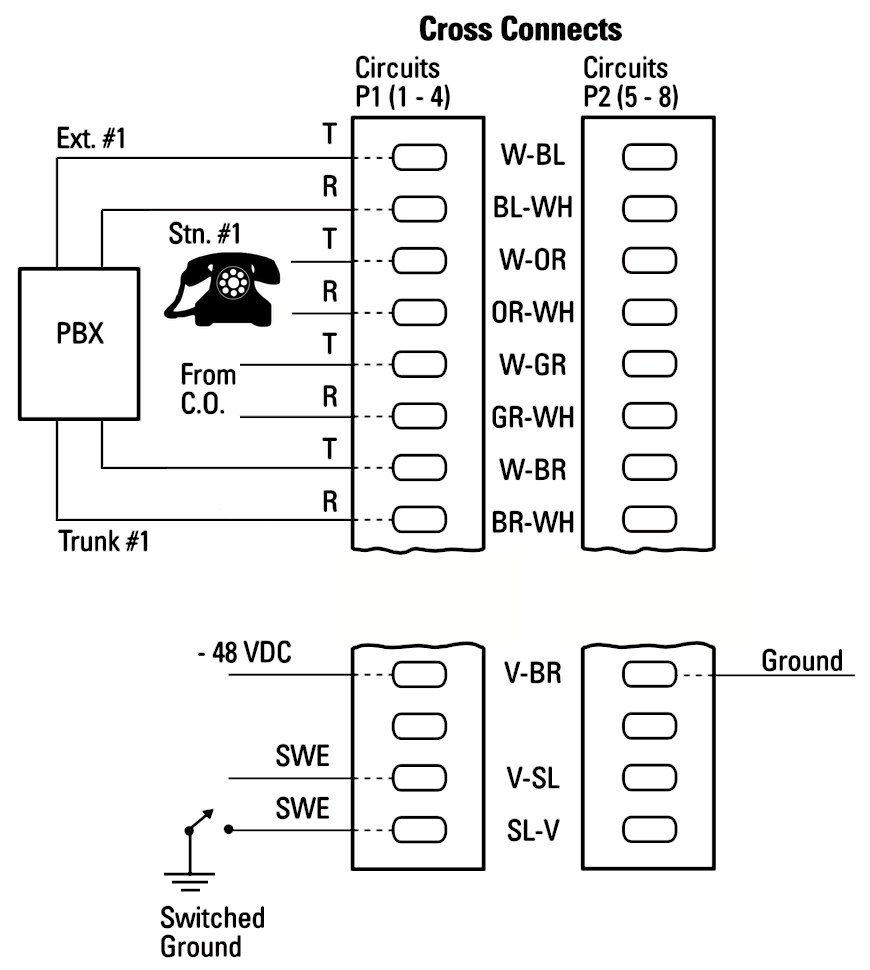
Typical Wiring:
Identify the appropriate Power Fail block, and run jumpers as described below. Each single power fail by-pass circuit will require up to 4 jumpers. Each 25 way block supports just 4 by-pass circuits. Each unit supports 8 circuits (P1 and P2).
- 1st pair ➤ PBX station TN - connects to the analog PBX port TN
- 2nd pair ➤ Station Cable - connects to the analog phone
- 3rd pair ➤ PTT trunk - connects to the CO trunk
- 4th pair ➤ PBX trunk TN - if the trunk is shared with the PBX, run this to the trunk port TN.
- Power is supplied on pin 49 of both connectors, P1: negative - P2: positive (PBX ground must also be tied to Pin 24 of P2).
- To remotely Activate Bypass, ground pin 50 (SWE) of connector P1
Note: If a Shumway SBI-217-25 (42VDC @ 300mA) pair is used to supply power to a DEES Models 154, Tip connects to P1 pin 49, Ring connects to P2 Pin 49.
Meridian System Monitor wiring:
- the power-fail-transfer unit can interface with a M1 System monitor or console:
NT8D22 System Monitor:
- Ground pin 8 of NT8D46BH cable
- Connect pin 7 to P1 pin 50 (SWE)
NT7D15 System Monitor (Option 21A):
- Ground pin 9 of NT8D46BH cable
- Connect pin 4 to P1 pin 50 (SWE)
M2250 Attendant Console Activation:
- Ground pin 36 of the console cable
- Connect pin 11 to P1 pin 25 (SWE)
BIX Label:
Download the template: PFTU DCE Model 154 ![]()

Operation:
Normally, both station and CO trunk station are connected to PBX ports.
On power-fail, the station is directly connected to its associated CO trunk.
- Station ➤ PBX TN
- CO trunk ➤ PBX TN
Station has PBX dial-tone.
Power-fail:
- Station ➤ CO trunk
- PBX TN's ➤ N/C
Station has CO dial-tone.
Model 154, 154A Notes:
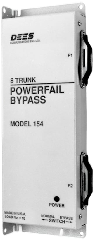
DEES Models 154 (48VDC) and 154A (24VDC) provide bypass for up to 8 analog trunks during a PBX or power failure. Multiple units can be connected to handle more than 8 trunks.
Units can be activated by power failure, a manual bypass switch, or a ground from a local or remote location. The Model 154 can also control auxiliary equipment via two sets of relay contacts (NO and NC).
In the event of a PBX power failure, the Bypass Interface automatically switches eight C.O. trunks directly to preselected stations, bypassing the PBX.
When bypass is no longer required, a loop usage monitor circuit restores only the
idle trunks.
Active trunks remain in bypass mode until completion of the present call, and are then restored.
Presence of power at the PBX is indicated by a red L.E.D. mounted on the front of the unit. Red indicates non-bypass mode.
A manual switch allows local control of the Bypass. The normal position allows control by the presence of power at the PBX, the bypass position puts all 8 channels into the bypass mode.
Two 25 pair industry standard Amphenol (male) connectors on the side of the unit provide all connections required for C.O. Trunks, PBX Trunks, Station Telephones and PBX Extensions.
P1 Wiring
| Pin | Wire | Colour | Des | |
|---|---|---|---|---|
| 26 1 |  |
White-Blue (Tip) Blue-White (Ring) |
EXT | 1 |
| 27 2 |  |
White-Orange Orange-White |
STN | |
| 28 3 |  |
White-Green Green-White |
CO | |
| 29 4 |  |
White-Brown Brown-White |
TRK | |
| 30 5 |  |
White-Slate Slate-White |
EXT | 2 |
| 31 6 |  |
Red-Blue Blue-Red |
STN | |
| 32 7 |  |
Red-Orange Orange-Red |
CO | |
| 33 8 |  |
Red-Green Green-Red |
TRK | |
| 34 9 |  |
Red-Brown Brown-Red |
EXT | 3 |
| 35 10 |  |
Red-Slate Slate-Red |
STN | |
| 36 11 |  |
Black-Blue Blue-Black |
CO | |
| 37 12 |  |
Black-Orange Orange-Black |
TRK | |
| 38 13 |  |
Black-Green Green-Black |
EXT | 4 |
| 39 14 |  |
Black-Brown Brown-Black |
STN | |
| 40 15 |  |
Black-Slate Slate-Black |
CO | |
| 41 16 |  |
Yellow-Blue Blue-Yellow |
TRK | |
| 42 17 |  |
Yellow-Orange Orange-Yellow |
||
| 43 18 |  |
Yellow-Green Green-Yellow |
||
| 44 19 |  |
Yellow-Brown Brown-Yellow |
||
| 45 20 |  |
Yellow-Slate Slate-Yellow |
||
| 46 21 |  |
Violet-Blue Blue-Violet |
||
| 47 22 |  |
Violet-Orange Orange-Violet |
||
| 48 23 |  |
Violet-Green Green-Violet |
||
| 49 24 |  |
Violet-Brown Brown-Violet |
Power (neg) |
|
| 50 25 |  |
Violet-Slate Slate-Violet |
SWE SWE |
|
P2 Wiring
| Pin | Wire | Colour | Des | |
|---|---|---|---|---|
| 26 1 | |
White-Blue (Tip) Blue-White (Ring) |
EXT | 5 |
| 27 2 | |
White-Orange Orange-White |
STN | |
| 28 3 | |
White-Green Green-White |
CO | |
| 29 4 | |
White-Brown Brown-White |
TRK | |
| 30 5 | |
White-Slate Slate-White |
EXT | 6 |
| 31 6 | |
Red-Blue Blue-Red |
STN | |
| 32 7 | |
Red-Orange Orange-Red |
CO | |
| 33 8 | |
Red-Green Green-Red |
TRK | |
| 34 9 | |
Red-Brown Brown-Red |
EXT | 7 |
| 35 10 | |
Red-Slate Slate-Red |
STN | |
| 36 11 | |
Black-Blue Blue-Black |
CO | |
| 37 12 | |
Black-Orange Orange-Black |
TRK | |
| 38 13 | |
Black-Green Green-Black |
EXT | 8 |
| 39 14 | |
Black-Brown Brown-Black |
STN | |
| 40 15 | |
Black-Slate Slate-Black |
CO | |
| 41 16 | |
Yellow-Blue Blue-Yellow |
TRK | |
| 42 17 | |
Yellow-Orange Orange-Yellow |
||
| 43 18 | |
Yellow-Green Green-Yellow |
||
| 44 19 | |
Yellow-Brown Brown-Yellow |
||
| 45 20 | |
Yellow-Slate Slate-Yellow |
||
| 46 21 | |
Violet-Blue Blue-Violet |
||
| 47 22 | |
Violet-Orange Orange-Violet |
||
| 48 23 | |
Violet-Green Green-Violet |
NO NO1 |
|
| 49 24 | |
Violet-Brown Brown-Violet |
Power (pos) PBX Ground |
|
| 50 25 | |
Violet-Slate Slate-Violet |
NC NC1 |
|
- NO: Normally Open Dry Conacts
- NC: Normally Closed Dry Conacts
- SWE: Switch Enable (GND = Active)