M2250 Console Wiring

Cross-connect:
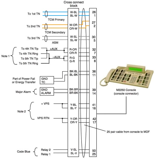
A 25 pair console cable is punched down as follows:
| TCM | TCM | ASM | AUX | AUX | ← Console | ||||||||||||||||||
|---|---|---|---|---|---|---|---|---|---|---|---|---|---|---|---|---|---|---|---|---|---|---|---|
| 1 | 2 | 3 | T4/5 | R4/5 | ← PBX TN | ||||||||||||||||||
Note: AUX Power TN's 4 & 5 are split: TN Tip's to pair 7 (AUX +), TN Ring's to pair 8 (AUX -).
Notes:
1. The M2250 is powered from the line circuits. In addition to the Primary TN, Secondary TN, and ASM TN, two TNs are cabled to the M2250 using the AUX pairs. Note, AUX Power pairs are split: Tip's to pair 7 (AUX +), Ring's to pair 8 (AUX -).
2. The third TN (TYPE: PWR) must be cross-connected to the console cable WH/SL pair whether or not an ASM (Attendant Supervisory Module) is installed. This third TN provides additional console power, required with long loop lengths.
3. When BLF or display backlight options are used, an additional 16V dc power supply is required. The 16V dc source is cabled through +VPS and +VPS RTN leads. The maximum distance from the console to the power source is 35 meters.
4. It is recommended to use five consecutive TN's for each console, though one power TN (TYPE: PWR) is often enough.
5. The maximum loop length is 900m (24 AWG wire). Generally, AUX power is not needed for cable runs under 100m.

CAT5:
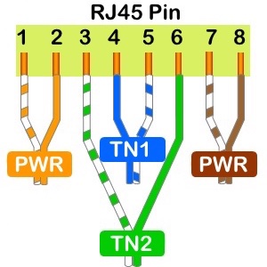
To extend a basic console (no BLF) with a standard four pair CAT5/6 cable, use:
- Pairs 1 and 3 = TN 1 and 2 for Console pairs 1 and 2 (568B: Blue/Green).
- Pairs 2 and 4 = PWR TN's maybe needed for Console pairs 5, 7 and 8 (568B: Orange/Brown).
(AUX PWR is optional. The tips of AUX power TNs goto Console pair 7, the rings to Pair 8).- Generally, power TN's are not needed for cable runs under 100m.
See also: M2250 Console Programming.