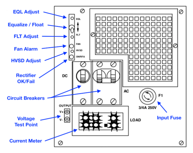
MPR25 Front panel
- Float / equalize control
- A momentary switch. When held in the EQL position, the rectifier changes to equalize mode and boosts the output voltage to the value set by the EQL potentiometer. Otherwise, the rectifier delivers a float voltage set by the FLT potentiometer. The output voltage can be measured at the Test Points.
- Indicator LEDs
RFA/ON: Rectifier Failed (or no load) Rectifier operational Fan: Fan failure - Rectifier failure alarm (RFA)
- Indicates an internal failure, or a no load condition. When the rectifier operates in parallel with other rectifiers and its output voltage is adjusted lower, the RFA LED will change to RED. Rotating the FLT potentiometer slightly clockwise will make the RFA LED illuminate green.
- Fan failure alarm
- A fan failure will activate the fan alarm and inhibit rectifier operation. An RFA alarm will occure upon a rectifier fault.
- High voltage shut down (HVSD)
- If the rectifier output voltage exceeds a value (adjustable from -52 to -59.5 V) it shuts down immediately, locks out, and indicates an RFA. This function is not dependent on the output load condition. The rectifier is reset from an HVSD condition by cycling the AC circuit breaker.
- DC / AC Circuit Breakers
- Locally turn the rectifier ON/OFF and disengage it from the DC circuit. Overrides any remote control signals.
- Input fuse (F1)
- A 3/4 A, 250 V fuse to protect against high inrush currents. Failure of this fuse during operation will disable the unit.
- Test points (V+, V-)
- Allow the user to measure the voltage at the point of regulation, whether the DC breaker is ON or OFF. A 10 K resistor is placed in series with the –48 V lead to prevent short circuits at the jack terminals.
- Current meter
- A three-digit output current meter. The load share amperage for each rectifier must be equal, set by the FLT potentiometer, and be at least 3 amps (ie, 9 A for three rectifiers) for best results. Maximum output is automatically current limited to 25.5 to 30 A.
