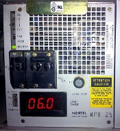
MPR25 Load Balancing

This is a maintenance task: Rectifiers must be load shared.
- eg: each rectifier should supply approximately the same load current.
Make sure all MPR25 AC and DC breakers are ON, and indicating a load current.
Note: When adding or replacing a rectifier, always set DC and AC circuit breakers OFF.
24 x 2.25 VPC = 54 VDC system float voltage. Always refer to the battery vendors information.
Balancing:
The system float voltage should typically be 53-54 VDC, displayed on the MFA150 front panel.
Balance the rectifiers up or down, depending on if the system float voltage is a little high or low:
If the system float voltage is low:
- Identify the “lowest reading rectifier”, from its front panel amp meter.
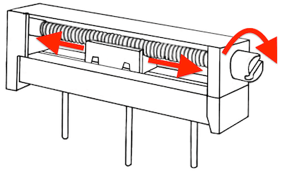
- Carefully turn the FLT potentiometer clockwise to increase the current. The voltage will increase by a SMALL amount.
Continue past the mean value indicated by the other rectifiers, but DO NOT exceed 20 Amps (front panel display). - Turn your attention to the next “lowest reading rectifier”, and repeat until the system float voltage approaches 54VDC.
If the system float voltage is high:
- Identify the “highest reading rectifier”, from its front panel amp meter.
- Carefully turn the FLT potentiometer anti-clockwise to decrease the current. The voltage will drop by a SMALL amount.
A red RFA LED indicates a load under 0.1 A. Rotating the FLT potentiometer slightly clockwise will clear the alarm (green). - Turn your attention to the next “highest reading rectifier”, and repeat until the system float voltage approaches 53VDC.
Adjust the individual FLT potentiometer as needed to balance the current delivered by each rectifier, so the load share amperage for each rectifier is equal. It is recommended that the current from each rectifier be at least 3 amperes for best operating results.
- Turn FLT potentiometer clockwise to increase the voltage/current.
- Turn FLT potentiometer anti-clockwise to decrease the voltage/current.
Potentiometers are threaded, and will typically turn 15-25 times from one end to the other. Turn it slowly. It looks like nothing is happening, and then suddenly BAM! 25 amps, and you have to quickly back it off again! Adjustment can be a bit touchy if the resistive track or wiper path is dirty.
If a High Voltage Shut Down trips, the RFA (Rectifier Fail Alarm) LED lights RED and the rectifier locks out. Turn the HVSD (High Voltage Shut Down) potentiometer 2 turns clockwise, reset the MPR25 breakers (off and back on), and continue with the FLT adjustment. Repeat this adjustment if the MPR25 trips again.
Note: Some rectifiers may indicate an RFA (red RFA led). A red RFA indicates a rectifier delivering less than 0.1 A. Rotating the float potentiometer (FLT) slightly clockwise will make the LED illuminate green.
