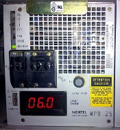
MPR25 Rectifier Adjustment

The following steps are necessary to adjust and align Nortel MPR25 Rectifier groups used in DC power (battery) PBX installations.
These steps may be performed under load (i.e., with Switch, Inverters, etc. powered on).
The adjustments must be performed in two stages. First each individual rectifier must be adjusted, and then the rectifiers must be aligned as a group (load balancing).
Note: The final 'group' adjustments should be repeated as a periodic routine maintenance.
Tools required: Multi-Meter (set to DC volts), and a small flat blade screwdriver.
Preliminary 'Individual' Adjustments:
Repeat the following procedure for each MPR25 in your system.
For the unit being adjusted, set the DC breaker OFF (left) to take it off-line, and the AC circuit breaker ON (right).
- Place the multi-meter test leads into the front panel test points (V+, V-), and measure DC voltage.
- Turn the HVSD (high voltage shut down) potentiometer 10 full turns clockwise.
- Adjust the FLT (float charge) potentiometer for approximately –57 VDC (HVSD voltage).
- Patiently turn the HVSD potentiometer counterclockwise until the rectifier shuts down.
- Turn the FLT potentiometer a further 2 full turns clockwise.
- Cycle the AC breaker OFF/ON. The unit should power up, and remain on.
- Adjust the FLT potentiometer for –52.6 VDC (float voltage).
- Holding the FLT/EQL switch in the EQL position, adjust the EQL (equalize-charge) potentiometer for –53.8 VDC.
If no voltage is indicated, check the front panel fuse F1 (3/4A, 250V), and replace if necessary.
This completes the preliminary adjustment of one unit.
Final 'Group' Adjustments (Load Balancing):
Upon completion of the preliminary 'Individual' adjustments, turn all of the rectifiers on.
Note: The battery voltage must be below the rectifier(s) float voltage for the rectifier(s) to come on-line - i.e., the red LED display on the MFA150 must read less than –54 VDC before any final adjustments can be made.
To equally balance the load between rectifiers, some fine FLT adjustment may be necessary. Turn the FLT potentiometer VERY SLIGHTLY until the indicated current on the MPR25 front panel LED displays are similar - i.e. within ± 0.2 of each other.
- If the current is too low, turn FLT Clockwise to increase it.
- If the current is too high, turn FLT Counterclockwise to reduce it.
Observe the system voltage (MFA150), and make sure it remains within spec. Increase the FLT potentiometer of the lowest current rectifier, or reduce the FLT potentiometer of the highest current rectifier to bring the system float voltage up or down respectively.
This adjustment must be repeated until all rectifiers are equally loaded.
Replacing an MPR25 Rectifier:
Before adding or replacing a rectifier, verify that the rectifier DC and AC circuit breakers are in the OFF position.
Turn the FLT Adjust several turns counterclockwise before inserting a replacement unit, rectifiers are hot swappable.
If the new unit immediately trips with a Rectifier Failure Alarm (RFA: Red LED), turn HVSD two turns clockwise and reset the breaker. Repeat until the LED is Green. If the RFA LED is Red without triping the breaker, rotate FLT clockwise until the LED goes green.
Now slowly rotate the FLT Adjust until the Current Meter indicates a value similar to the other rectifiers (load balancing).
See also: Replacing M1 Batteries