Replacing M1 Batteries
The Meridian 1 DC-powered systems require an external DC power plant consisting of rectifiers (also called chargers or AC/DC converters) and power distribution and control equipment. This equipment continuously charges a large bank of batteries and distributes the DC power to each column.
| Meridian 1 DC Power Input Specifications | |
|---|---|
| Maximum range: | -42 to -56.5 V |
| Expected nominal (24 stationary cells): | -52.08 V |
| Expected nominal (23 sealed cells): | -51.75 V |
| Expected nominal (24 sealed cells): | -54.00 V |
If the battery bank sits on float for 15 years, and is rarely or never exercised, it will fail you in its moment of need.
If you see signs of wear, such as bulging, cracked, or leaking cells, you should replace it, or find an alternate solution.
Battery Bank Voltage
A DC powered PBX requires a nominal -54 volt supply, from a large battery bank. This is usually derived from 24 x 2.25 volt cells strapped in series. Sometimes the cells are strapped as 4 x 13.5v, where the 13.5 volt pack is made from 6 x 2.25 volt cells. The way they are strapped doesn't really mater, but what does matter is the cell voltage, number of cells, and the final voltage.
| Battery configuration | Float voltage (V) | Equalize voltage (V) | ||
|---|---|---|---|---|
| Cell | Bank | Cell | Bank | |
| 24 stationary cells | -2.17 | -52.08 | -2.25 | -54.00 |
| 23 sealed cells | -2.25 | -51.75 | -2.35 | -54.05 |
| 24 sealed cells | -2.25 | -54.00 | -2.35 | -56.40 |
Obviously, when assessing the suitabiility of replacement cells, look very carefully at the manufacturers specifications.
- Unigy 2 cells are rated at 2.25 VPC (volts per cell). Multiplied by 24 = 54 V nominal float voltage.
A lead acid cell can measure at anything between 2.15 and 2.35 volts. Multiplying this by 24 gives a voltage between of 51.6 and 56.4 volts, and the upper voltage is too high. You can drop the charge voltage to 54 volts (2.25 per cell), but doing so may adversely affect performance. A charge voltage below 2.1 volts per cell will cause sulfation and render the battery useless.
PBX battery replacement specialists know this, and may therefore provide either a 23 cell bank, or a special 5 cell (10 volt) pack to be used with three conventional 6 cell (12 volt) packs.
- We can then make our PBX battery bank using three 6 cell packs and one 5 cell pack, or a total of 23 cells and 54.05 volts: 2.35 x 18 = 42.3 plus 2.35 x 5 = 11.75 --- (42.3) + (11.75) = 54.05 volts.
Your choice of replacement battery pack will be influenced by voltage and availability, but the bank voltage must not exceed the specified maximum DC input voltage (56 volts). Check (and follow) the manufacturers guidelines on recommended float voltage.
Replacing the Battery Bank
Always select deep-cycle sealed (non-venting) lead acid gel type replacement batteries.
You can replace the batteries with the PBX 'online', without service interruption.
- Throw the 'battery isolation breaker' OFF - the PBX will continue to run from the MFA150 / MPR25 stack.
DO NOT WORK ON CONNECTIONS WITH BATTERY CONNECTED TO CHARGER OR LOAD.
- Replace the battery bank with the new cells, making sure that the cables will reach the terminals.
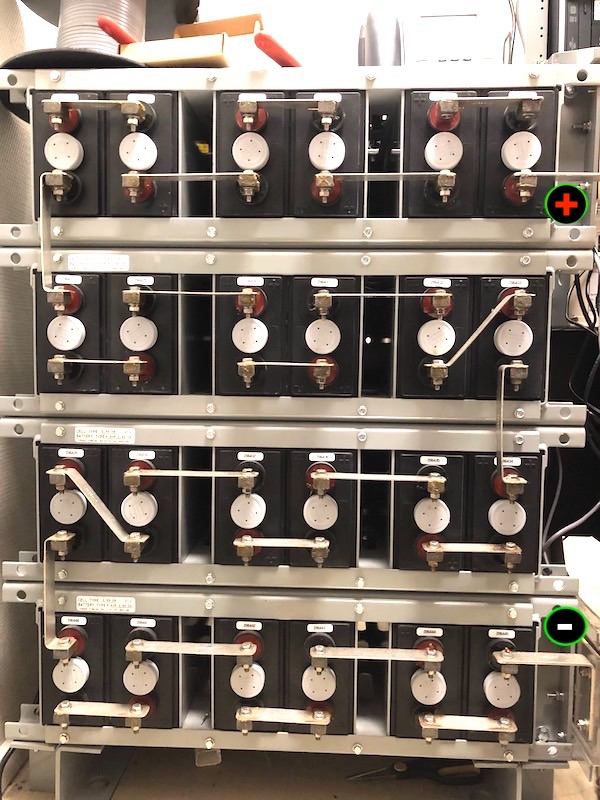
Old battery bank, plus at the top
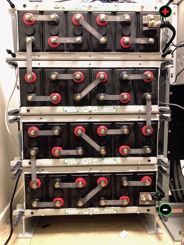
New battery bank, plus at the top
- Check the voltage and polarity with a meter and be sure its correct (!) before putting the battery bank online.
- Throw the 'battery isolation breaker' back ON, putting your new bank on-line.
- Check the MFA150 voltage and MPR25 current readings.
 |
Pay special attention to polarity! Nortel uses BLACK for POSITIVE and RED for NEGATIVE
Phone systems are positive ground, which means the battery positive lead is strapped to ground. Making a mistake with power can make for a very bad day! Always check, and double check your work. |
An alternative solution for smaller systems, is to use 4 x 12V batteries:
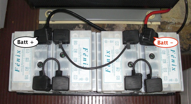
4 x 12 Volt batteries in series. Do not exceed the DC Input Specifications.
The UPS Alternative
Batteries are expensive, heavy, you can't ship them, and you can't throw them away. So, whats the alternative?
Well, we can replace the battery bank function with a 220v UPS feeding the MFA150 / MPR25 stack. We can then isolate (via the 'battery isolation breaker') the batteries - and then subsequently remove them. The MFA150 / MPR25 stack will power the PBX, the UPS will supply (220v) backup power to the MPR25's. Depending on the system size, this may be the more 'cost effective' solution.
To calculate a suitable UPS size, we need to work out our requirements:
- The Power Required by the load - measured in DC Watts, or Volt-Amps (VA)
- The time deemed necessary to maintain this load - measured in Amp-Hours (Ah).
Power: Multiply voltage (54 volts) by amps, as displayed on the MFA150 - this gives us the DC watts (Volt-Amps) being drawn by our system. Multiply this figure by 1.4 to derive the AC equivalent (power-factor corrected) Volt-Amp (VA) value. Our UPS should be rated 30-50% above this value. Generally, each Meridian 1 column will consume 1-2KVA (an Option 11 is maximum 500VA per cabinet).
Run time: Do you want to survive a brown-out or a long power outage? How long should the UPS be able to supply its load? UPS runtime is a ratio of battery capacity (AH) over load current (A): Time = AH / A. Refer to the manufacturers UPS discharge curve.
Note: Do not confuse the output rating of the rectifiers in DC amps with input requirements in AC amps.
- Power down the PBX. Unfortunately this can not be done online.
- Disconnect (isolate) the batteries via the 'battery isolation breaker'.
- Connect the UPS fed 220VAC to the AC input on the top MPR25 shelf (NT5C10CH). The AC input terminals are on the left-hand-side viewed from the front (shown right). Connect Live (Hot) to L1, Neutral to L2.

Power is connected on the left side →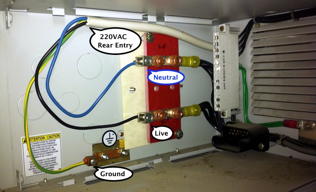
NT5C10CH - 220VAC Power Input connections - Apply AC power to the MPR25 stack, and confirm correct operation (a nominal 54VDC output)...
- Power up the PBX via the column breakers on the MFA150 front panel.