CallBill Installation Procedure
How to install the CallBill modules depending on the preferred CallBill configuration. Each CallBill module has a folder on the Setup CD. To complete the installation, run the upgrade file from the site disk if supplied. The following is from Phoneware's documentation.
Logger / Transfer Modules
Description
The Logger module is responsible for collecting call records from the telephone system and storing them locally until the Record Processor module retrieves them using the Transfer Module. The Transfer Module is responsible for transferring the call records, collected by the Logger Module, to the Record Processor Module and for this reason the Transfer Module is also installed on the Logger Module PC. Once the call records are retrieved, they are archived locally on the Logger Module PC.
Minimum PC Specification
- Pentium III Processor
- 64 MB RAM
- Operating System: Windows XP, Windows 2000, Windows NT, Windows ME, Win 98, Win 95
- 1 Free Serial Port if connected directly to the telephone system
- 1 Modem Connection if connection to Record Processor Module is dial-up
- 1 Network Connection if connection to Record Processor Module, and/or telephone system, is via ethernet
Installation Procedure
- On the CallBill Setup CD, run LOGGER\SETUP.EXE which installs the Logger files in a directory of your choice (the default directory is C:\Callbill\).
- Verify that the communications link to the Meridian is functional using either Windows Terminal or Hyperterminal (or some other communications software). Note the communications settings used when connecting to the Meridian, as these will have to be set in the Logger Module later. Note: The only service required on the Meridian CDR port is CTY. No other services should be assigned to the port. Refer to CDR Programming for TTY port configuration.
- Run the Logger from the Program Group, or from the Start Menu, or run logger.exe from the Logger directory chosen in Step 1. Click Cancel on the window that appears or click the Esc button before the timer expires.
- On the Logger Module Menu bar, select the File menu -> Site Details option. The Site Details window will be displayed:

- On the Site Details window, enter a name for the site in the Name textbox. Select the Telephone System type from the drop-down list. Entry of details in the Address, Contact Name and Contact Number textboxes on this window is optional.
- Click the Save button to save the site details and click the OK button.
- On the Connection menu select the Telephone System option. The Telephone System Connection window will be displayed:
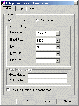
- Select the connection method to be used for connecting the logger PC to your switch. If the Comm Port option is chosen select the appropriate communication settings. The parameters required are Baud Rate, Parity, Data bits and Stop bits. If the Port Server option is chosen enter the Host IP address and the Port Number.
- When all the connection details are entered click the Save button and then click the OK button.
- Start call logging by selecting the Start Call Billing option from the Billing Menu.
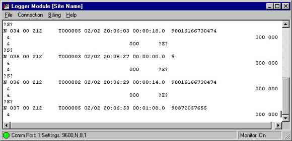
- Verify that the CDR records are being displayed in the correct format on the Logger Module's communications window, shown below.
If you're unsure of the correct format, refer to CDR Programming, and/or CDR Setup.
- Run the Transfer Module from the Program Group, or from the Start Menu, or run CB_XF.exe from the Transfer Module directory chosen in Step 1.
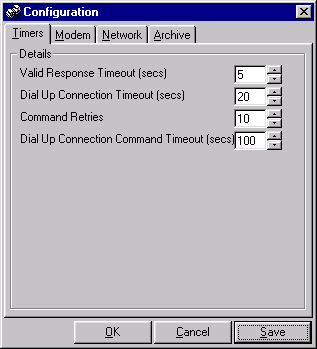
- To establish the Record Processor Module connection method to the Transfer Module select File menu, Settings option. The Configuration screen will be displayed:
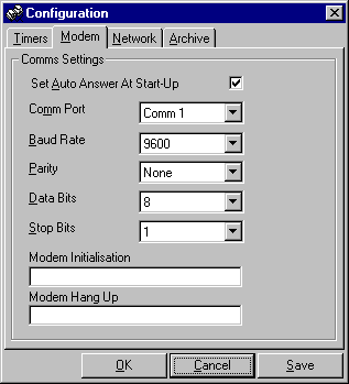
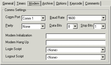
(a) If using the modem connection method, click on the modem tab (shown below). Enter the communication parameters i.e. Comm Port, Baud Rate, Data bits, Parity and Stop bits and ensure the Set Auto Answer At Start-up option is checked.
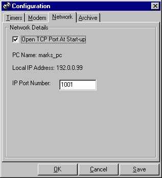
(b) If using the network connection method (shown below), click on the network tab. Enter the port number (default port number is 1001). Ensure that the Open TCP Port At Start-up option is checked. Click the Save button and then click the OK button at the bottom of the screen.
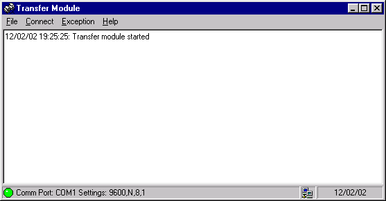
- Restart the Transfer Module. Verify that the status bar at the bottom of the screen is displaying "Comm Port: COM1 Settings: 9600, N, 8, 1" if using the modem connection or "TCP Port Open (Port 1001)" if using the Network Connection method, as shown below:
Record Processor
Description
The Record Processor Module is responsible for retrieving call records from the Logger Module and storing these call records in a CallBill site database. The cost of each call is calculated during processing and is based on tariffs applicable to the site from which the records were retrieved. The Record Processor can be configured to periodically retrieve call records from multiple sites.
Minimum PC Specification
- Pentium III Processor
- 128 MB RAM
- Operating System: Windows XP, Windows 2000, Windows NT, Win 98
- 1 Modem Connection if connection to Logger Module is dial-up
- 1 Network Connection if connection to Logger Module is via network
Installation Procedure
- Connect the CallBill security dongle to the PC parallel port.
- From the CallBill Setup CD, run Record Processor \SETUP.EXE. This installs the Record Processor files in a directory of your choice (the default directory is c:\callbill\rec_pro).
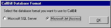
- Select the Database format for use with Callbill, as shown:
Site Disk Available
- Run the self-extractor file on floppy disk to extract the site information to the Record Processor databases.
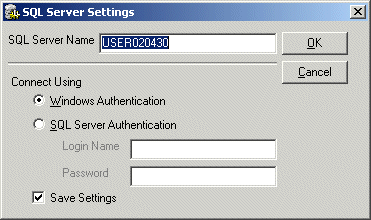
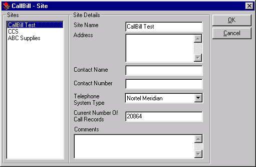
- Run the Record Processor from the Program Group, or from the Start Menu, or run cb_rp.exe from the Record Processor directory chosen in Step 1. If you have chosen Microsoft SQL Server in Step 3, a SQL Server Settings dialog will be displayed, refer to Figure 7. Enter the SQL Server Name and Connection Settings. If the SQL Authentication is accepted or if Microsoft Jet Access was chosen in Step 3, the Site window will be displayed (shown below). Confirm that the Site Details information is correct.
- If the information is correct, click the OK button to close the Site window.
Site Disk Not Available
- Run the Record Processor from the Program Group, or from the Start Menu, or run cb_rp.exe from the Record Processor directory chosen in Step 1. If you have chosen Microsoft SQL Server in Step 3, a SQL Server Settings dialog will be displayed, refer to Figure 7. Enter the SQL Server Name and Connection Settings. If the SQL Authentication is accepted or if Microsoft Jet Access was chosen in Step 3, the Site window will be displayed:
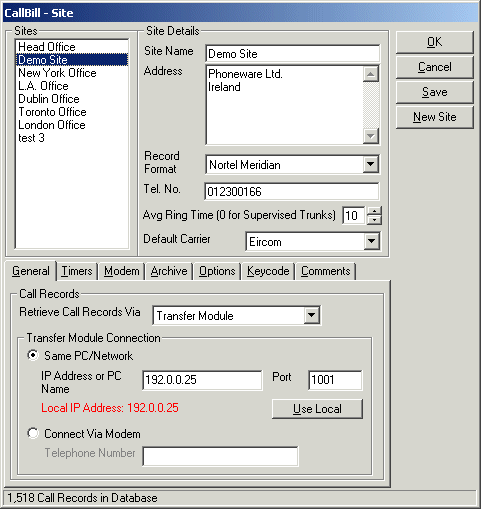
- Select the New Site button to create a new site. The new site screen will be displayed, as shown. Enter a Site Name and the local Telephone Number and click the Save button. The site ID will be displayed. Note that the site ID should match the licence site ID provided by Phoneware and click the OK button.

- Select the Record Format option and choose the correct format.
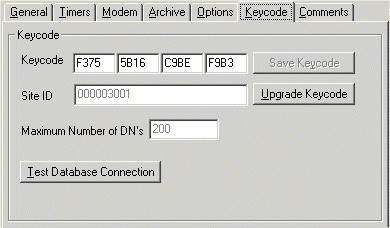
- Select the Keycode tab, as shown below, and enter the 16-digit hexadecimal keycode provided by Phoneware in the 4 keycodes textboxes on the Site screen. Click on the Save Keycode button at the bottom right hand side of the screen. A dialog box confirming the Site ID and licensing for which the keycode was issued is displayed. If this is correct, click the YES button. If it is incorrect, click the NO button and contact Phoneware to have the keycode checked.
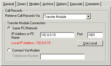
- Select the General tab, and enter the connection method for communication with the Transfer Module.
- If connection method to Transfer Module is via Same PC/Network, enter the IP Address or PC Name and the assigned Port number of the Transfer Module PC:
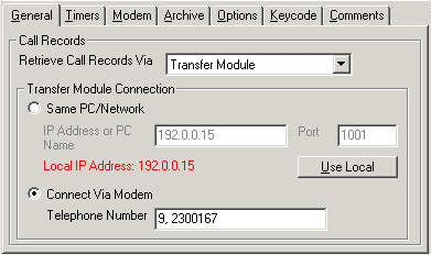
- If connection method to Transfer Module is via Connect Via Modem method, enter the Telephone Number. Select the Modem tab and set the modem communication parameters:
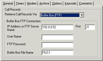
- If connection method is via the Buffer Box (FTP), enter the IP Address or name of the FTP Server where the Buffer Box (FTP) for the selected site is located. Enter the number of the port for communication with the Buffer Box (FTP). The default port number is 21 but if this has been changed on the Buffer Box (FTP) it must also be changed here. If security protected, enter the User Name and the FTP Password of the Buffer Box (FTP). The Buffer Box (FTP) consists of memory blocks, enter the name of the file where the records are stored.
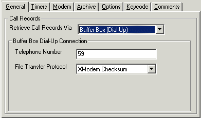
- If connection method is via the Buffer Box (Dial-Up), enter the telephone number of the Buffer Box for the current site. The File Transfer Protocol is the method used to transfer data from the Buffer Box to the Record Processor. The default setting is XModem Checksum.
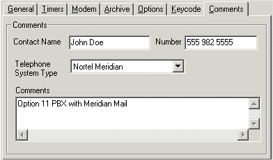
- Select the Comments tab, as shown below, and enter the Telephone System Type and contact details.
- Click the Save button to save the settings and then click the OK button.
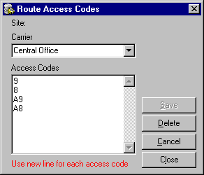
- On the File menu, select Route Access Codes. The Route Access Codes window, below, will be displayed. Choose the Carrier option and select the correct carrier. Enter the route access codes output on the Meridian CDR data for this carrier in the Access Codes textbox (use a new line for each access code). Click the Save button and click the Close button.
- On the File menu, select Schedules. Click the New button to create a recurring schedule to transfer the CDR details from the Logger Module via the Transfer Module. The Schedule screen will be displayed, as shown in Figure 14.
- Enter a schedule name in the Name textbox.
- Set a schedule start date and time.
- Enter a valid log file name.
- Select the Schedule Type option and select the required option.
- Click the ADD button and add the correct logger module sites.
- Click the Save button and click the Close button.

Reports Module
Description
The Reports Module allows the user to retrieve information from the CallBill databases by running reports. These reports can either be run ad hoc or they can be attached to a schedule, which will run them automatically when the schedule activates.
Minimum PC Specification
- Pentium III Processor
- 128 MB RAM
- Operating System: Windows XP, Windows 2000, Windows NT, Windows ME, Win 98
- 1 Network Connection if CallBill databases are not on the same PC
Installation Procedure
- From the CallBill Setup CD, run Reports Module\SETUP.EXE. This installs the Reports Module files in a directory of your choice (the default directory is c:\callbill\rec_pro).
- Run the Reports Module from the Program Group, or from the Start Menu, or run cb_rpts.exe from the Reports Module directory chosen in Step 1.
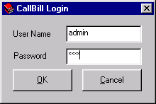
- If you have chosen Microsoft SQL Server in the Record Processor setup, an SQL Server Settings dialog will be displayed, refer to Figure 7. Enter the SQL Server Name and Connection Settings. If the SQL Authentication is accepted or if you have chosen Microsoft Jet Access in the Record Processor setup, the Reports Module will display the CallBill Login window, below. The default Username is "ADMIN" and the Password is "0000".
- Verify the Site details on the Site window, as shown below, and click the OK button to close.
- Use CallBill's Context Sensitive On-Line Help facility to learn about the features and facilities provided by CallBill.
- On a new installation the site database will not contain any call records until call processing has taken place. After call processing should have commenced, run a test report to verify.
Note: If you require technical support, contact: Phoneware's Technical Support Helpdesk:
| E-mail: | support@phoneware.ie |
| Telephone: | +353 404 68711 |
| US Toll Free: | 1-800 660 9248 |