Dual PRI Installation
(Large/CS1000M)

- For Small/CS1000E (IPMG systems), see PRI programming.
- Universal Digital Trunk (UDT) card, see UDT E1 PRI Example.
Hardware:
The following resides in the Core/Network module:
- NT5D97 - DDP2 PRI/DTI Card
- QPC775 - Clock Controller Card
- NT6D80 - MSDL card
Always use the ENB/DIS switch when inserting/removing cards.
Cables:

- DDP2 to QPC775 (clock) uses NTCG03 cables (shown right)
- DDP2 (J6) DCHI uses the NTCK80 (AA=6 feet, AB=18 feet, AC=35 feet, and AD=50 feet)
- DDP2 (J5) TRK uses NTCK45 (120 ohm, 8-feet) with two 9 pin male connections at the end
Note, the NTCG03 comprises a 9-pin adapter, with a 2-pair RJ11 line cord (rollover):
- 1 → 4
- 2 → 3
- 3 → 2
- 4 → 1
External connectors:
| Designator | Type | Description |
|---|---|---|
| Unit 0 Clock 0 | RJ11 | Connects ref. clock 0 to Clock Controller card 0 |
| Unit 0 Clock 1 | RJ11 | Connects ref. clock 0 to Clock Controller card 1 |
| Unit 1 Clock 0 | RJ11 | Connects ref. clock 1 to Clock Controller card 0 |
| Unit 1 Clock 1 | RJ11 | Connects ref. clock 1 to Clock Controller card 1 |
| J5 TRK | 9 Pin Female D | Two external E1's: Trunk 0 and Trunk 1 |
| J6 DCH | 26 Pin Female D | Connects to external DCH or MSDL card/port |
Faceplate LED's:
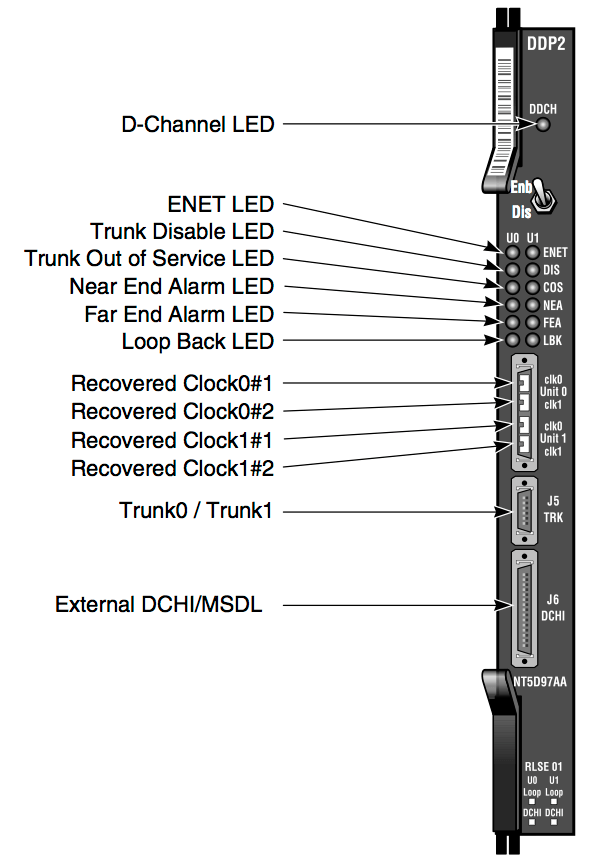
| Designator | Colour | Description |
|---|---|---|
| DDCH | // | NTBK51 status - Red:DIS / Grn:ENB / Off:Not Fitted |
| ENET | ENET 0 or ENET 1 is disabled | |
| DIS | Trunk 0 or Trunk 1 is disabled | |
| OOS | Trunk is out of service | |
| NEA | Local (Near End) Alarm | |
| FEA | Far End Alarm | |
| LBK | Loop Back test in progress on Trunk 0 or Trunk 1 |
Dip Switch Settings:
MSDL Settings: Choose a Port, all DCE to ON, all DTE to OFF (Use 422-A DCE)
DDP2 Settings: If using a Dual D-Channel daughter Board (NTBK51), you must set the MSDL device address.
| Trunk 0: |
S12_1- OFF-120 ohms (ON-75 ohms is used if using coax cable) S12_2- Spare S12_3- Spare S12_4- ON for PRI2/Off for DTI2 |
| Trunk 1: |
S7_1- OFF-120 ohms (ON-75 ohms is used if using coax cable) S7_2- Spare S7_3- Spare S7_4- ON for PRI2/Off for DTI2 |
Refer to the Circuit Card Reference NTP for full details.
NTCK45:
The NTCK45AA a cable is for systems equipped with an I/O filter panel, it connects the DDP2 faceplate J5 TRK port (P1, D-type 9 pin male) to the I/O filter (P2, P3 D-type 9 pin males), breaking out the two DDP2 trunks into two 9 pin D connectors.
| DDP2 (J5) | I/O Panel | Color | Description |
|---|---|---|---|
| P1-1 | P2-6 | Black | Trunk 0 TX Tip |
| P1-2 | P2-7 | Red | Trunk 0 TX Ring |
| P1-3 | P2-2 | Black | Trunk 0 RX Tip |
| P1-4 | P2-3 | White | Trunk 0 RX Ring |
| P1-5 | P3-6 | Black | Trunk 1 TX Tip |
| P1-6 | P3-7 | Red | Trunk 1 TX Ring |
| P1-7 | P3-2 | Black | Trunk 1 RX Tip |
| P1-8 | P2-3 | White | Trunk 1 RX Ring |

NTCK45
Trunk Pinouts:
Use the following table when hooking up, be prepared to swap RX and TX pairs!
| DB-9 (E1) (NT8D7217E6) | DB-15 (T1) | CSU/DSU * (RJ48/RJ45) | (T-568B) |
|---|---|---|---|
| 2 - Black/Transmit | 1 - White/Transmit | 1 - Transmit (R1) |  |
| 3 - Red/Transmit | 9 - Black/Transmit (could be 8) | 2 - Transmit (T1) |  |
| 6 - Black/Receive | 3 - Red/Receive | 4 - Receive (R) |  |
| 7 - White/Receive | 11 - Black/Receive (could be Yellow) | 5 - Receive (T) |  |
* DSU/CSU = Data Service Unit/Channel Service Unit, eg, the PTT modem.
Pinning a RJ45 to DB-9F Adapter:
Use the following adapter configuration with an E1, DB-9 end on the PBX (to NTCK45AA on J5).
You may need to reverse the TX / RX pairs - or swap orange & blue with T-568B (568A or 568B).
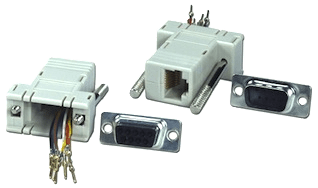
Note: Most RJ45 to DB-9F Adapters use this colour
scheme, but yours may not! Always check it first!
| RJ-45 | Colour | DB-9F |
|---|---|---|
| 1 | Blue | 2 |
| 2 | Orange | 3 |
| 3 | Black | |
| 4 | Red | 6 |
| 5 | Green | 7 |
| 6 | Yellow | |
| 7 | Brown | |
| 8 | White |
Loopback Adaptors:
- DB-9 (E1) - Loop pin 2 to pin 6, and pin 3 to pin 7
- DB-15 (T1) - Loop pin 1 to pin 3, and pin 9 to pin 11
- RJ45 (DSU) - Loop pin 1 to pin 4, and pin 2 to pin 5
Note: An RJ45 connector will fit an RJ48 jack, but the key on an
RJ48 connector will prevent it from plugging into an RJ45 jack.
Remember, the D channel will not establish on a loop test.
PBX Programming:
Step 1. CEQU
LD 17
| Prompt | Response | Description |
|---|---|---|
| REQ | CHG | |
| TYPE | CEQU | |
| PRI2 | X | New PRI Loop number = slot/position of NT5D97 card in network shelf |
Step 2. Build D- Channel
LD 17
| Prompt | Response | Description |
|---|---|---|
| REG | CHG | |
| TYPE | ADAN | |
| ADAN | NEW DCH # | Available D Channel Number |
| CTYP | MSDL | |
| DNUM | X (0-15) | Physical MSDL card address. All ports on the MSDL card share the same DNUM. |
| PORT | X (0-3) | Physical PORT number on MSDL card |
| DES | Description: used to identify the link, can be up to 16 alphanumeric characters | |
| USR | PRI | |
| IFC | EURO | Try EURO first- APAC may work in Asia |
| CNTY | ETSI | Country, ETSI = ETS 300: 102 basic protocol |
| CLID | OPT1 | OPT1 is the default for all EuroISDN interfaces |
| DCHL | X | PRI Loop Number |
| SIDE | USR | Prompted only if IFC = SL-1, ESIG or ISIG; one side is USR, the other NET |
| RLS | 25 | If not connecting to a Nortel CO switch-enter through |
| RCAP | COLP | Default for value for EUROISDN |
| OVLR | YES | Overlap Receiving Allowed |
| DIDD | 0 | Number incoming leading of digits to ignore during Overlap Receiving |
| OVLS | YES | Overlap Sending Allowed |
Step 3. Build Route
LD 16
| Prompt | Response | Description |
|---|---|---|
| REQ | NEW | |
| TYPE | RDB | |
| CUST | 0 | |
| ROUT | # | New Route Number |
| DES: | PRI1 | Designation |
| TKTP: | DID | |
| RCLS | EXT | |
| VTRK | NO | |
| DTRK | YES | |
| DGTP | PRI2 | |
| ISDN | YES | |
| MODE | PRA | ISDN Trunk Route (ISDN=yes) |
| IFC | EURO | Must match D-channel |
| CNTY | ETSI | Depends on the protocol of the CO |
| PNI | 1 | 1 if connecting to another PBX/0 if connecting to PTT |
| NCNA | YES | |
| NCRD | YES | |
| DSEL | VOD | May also try VCE |
| ICOG | IAO | In And Out call processing |
| SRCH | RRB | Round Robin or random selection of trunks |
| TRMB | YES | Trunk tromboning allowed |
| ACOD | 5601 | Access Code for the Route Dial Tone |
| TARG | 1 2 3 | These station TGAR's cannot access the ACOD |
| INC | (NO)/YES | YES only if using Incoming Digit Conversion |
| CDR | YES | Yes for CDR records on this route |
| INC | YES | |
| LAST | YES | |
| OAL | YES | |
| AIA | YES | |
| MUS | YES | Yes if Music Route is available |
| MRT | 21 | Music Route Number |
Step 4. Build Trunks
LD 14
| Prompt | Response | Description |
|---|---|---|
| REQ | NEW 30 | Build all 30 channels at once |
| TYPE | DID | |
| TN | X 1 | PRI Loop and Channel |
| DES | aaa..a | Designator, eg, PRI1 |
| CUST | 0 | |
| TRK | PRI2 | |
| PCML | A | Note: A for EURO-ISDN / MU for US, and switch to switch |
| NCOS | ||
| RTMB | # 1 | Route # and first member |
| CLS | DTN UNR | Don't forget tone dialing! |
Step 5. LPTI (Loop Timers)
Set CRC on/off. If you get Frame-slip errors, try changing this.
LD 73
| Prompt | Response | Description |
|---|---|---|
| REQ | CHG | |
| TYPE: | PRI2 | |
| FEAT | LPTI | Loop number of PRI card location or CEQU PRI2 defined loop |
| LOOP | L | Loop |
| MFF | CRC | Usually CRC, or maybe AFF - must match provider |
Step 6. SYTI (Clocking)
LD 73
| Prompt | Response | Description |
|---|---|---|
| REQ | CHG | |
| TYPE | PRI2 | |
| FEAT | SYTI | |
| CCO | ||
| PREF | L | Loop for CC0 primary clock reference |
| SREF | L | Loop for CC0 secondary (alternative) clock reference |
| CC1 | ||
| PREF | L | Loop for CC1 primary clock reference |
| SREF | L | Loop for CC1 secondary (alternative) clock reference |
Step 7. CLID
(NET_DATA)
LD 15
| Prompt | Response | Description |
|---|---|---|
| REQ | CHG | |
| TYPE | NET | NET_DATA |
| CUST | 0 | |
| ISDN | YES | |
| ENTRY | 0 | |
| HLCL | xx...x | Digits to be inserted before DN on CLID |
| DIDN | (YES)/NO | Set to NO so DN is not sent out/ Set to Yes so DN is sent out |
Note: LDN0 must be defined (LD 15) for ISDN PRI DID service. The length of LDN0 determines the number of trailing digits translated as the dialed DN on PRI DID routes.
Step 8. Clock Tracking
LD 60
| .TRCK PCK = Primary clock / SCLK = Secondary clock / FRUN = Freerun |
Step 9. PRI Startup
The MSDL / DCH will need a forced download (FDL) the first time its brought into service.
# = Loop Shelf Card on MGC systems.
LD 96
| STAT MSDL # |
| ENL MSDL # FDL |
| STAT MSDL # |
| ENL DCH X |
LD 60
| STAT |
| ENLL X (Loop) |
| STAT X |
| LCNT X |
| RCNT X |
| SSCK X (0 or 1 on a large system) |