Analog Lines & Trunks
By David Thompson
Issue 5.0, 8/99
Introduction
At the dawn of telephony, the majority of telephone wiring was installed by the
railroad companies of the time. Usually the cables were installed along side railroad
tracks and were referred to by the name of the tracks which they ran parallel. As shown in
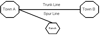
Figure 1, the tracks that ran between two towns were called "Trunk Lines"
because of the baggage (old sea trunks) that was carried over them.

Figure 1
When there was a switch in the tracks that led to a dead end (a ranch
for instance), that track was called a "Spur line"(Figure 2).

Figure 2
As telephony evolved, the names and terms became less associated with
their railroad roots, but the original circuit names stuck. As you can see in Figure 3,
The "Trunk Line" cables changed to "Trunk" and the "Spur
Line" cables changed to "Line". Notice how the trunk runs from a public
Exchange or Central Office (CO) to a Private Branch Exchange (PBX). In other words, a
trunk goes from switching system to switching system (CO to PBX, CO to CO or PBX to PBX).
The Line runs from a switching system and dead ends on a telephone. This is the basic
difference between a line and a trunk.

Figure 3
Key system and PBX Differences
In the early days of multi-line business telephones, there was a big difference between a Key System and a PBX. In order to access a line on a key system, the telephone had an appearance of the line on a button. Thus the line "dead ended" on the telephone. All trunks on a PBX terminated at the attendant console. The attendant then had to transfer a call to a station or extension on that PBX.
Today, with all the advancements in electronics, there is a real
"gray area" between key systems and PBXs. Most key systems today have many PBX
features and will allow special trunks that were previously only available on PBXs. These
key systems, half PBX and half key system are referred to as "Hybrids". Current
PBX’s have the features of original key systems, including key telephones with
programmable feature keys. A "built in" Key system.
Tip & Ring
The two wires that make up a basic line or trunk are labeled TIP and
RING. These terms came from the plugs on the old manual cord switchboards. Figure 4 shows
a plug from an old switchboard and how the wires that were attached to it got their name.
The Sleeve was an additional ground that is not used today.

Switchboard plug
Figure 4
The following text will identify the functional descriptions of loop start, ground start, E&M and DID analog trunk signaling as used between a PBX and a public Central Office. The descriptions will show all aspects of a call, incoming, outgoing, dialing and call completion.
Loop Start
Loop Start signaling over a 2-wire circuit is the most basic and common
type of signaling used in telephony today. It is the signaling used for standard
residential service and single line analog stations on PBXs.
The Tip side of the line is attached to ground and the Ring side is attached to
–48VDC (Figure 5)

Loop Start line, idle condition
Figure 5
When the telephone handset comes off the cradle, the associated hookswitch closes, or
makes contact. This allows current to flow through the circuit. The current sensor in the
CO/PBX "sees" the "loop current", Attaches digit sensing equipment and
sends Dial Tone. Dial Tone is a signal to the user that the CO/PBX digit receiver is ready
for dialing to commence (Figure 6).

Loop Start line, line seizure
Figure 6
An incoming call is originated when the CO/PBX sends ringing voltage, typically 90 - 105VAC, 30Hz superimposed over the -48VDC battery voltage. The ringing voltage is typically interrupted at 2 seconds on and 4 seconds off. The AC voltage passes across the capacitor, which blocks the DC voltage, and into the ringer (telephone) or ring detector (PBX) (Figure 7).
Note: The 90 – 105VAC ringing voltage (Ringing Battery) is sent at
20 – 40Hz. The frequency is reduced from the standard 60Hz of the American electrical
power grid. This was done to allow the mechanical ringers to resonate. As the AC current
switches direction, the bell clapper hits the bell. The lower frequency allows the bell to
resonate longer between bell claps, thus giving the bell a fuller sound.

Incoming Call
Figure 7
When the line rings, the PBX answers the call by closing the loop or
the user lifts the telephone handset thus closing the hookswitch. The CO senses the DC
loop current (closed hookswitch), removes the ringing voltage, and establishes an audio
path to allow the call to go through. When the PBX answers the call, it routes the call to
the appropriate telephone or an operator console and rings the instrument.
When either end opens the circuit, the call is disconnected. Typically, there is no additional signaling on loop start lines. However, some COs can send disconnect control. One type is called an Open Switch Interval (OSI). The CO disconnects the -48VDC for 500 milliseconds. Another control is called Line Disconnect Tone, Where the CO/PBX sends Dial Tone when the distant end hangs up. This disconnect control is useful for special devices such as Voicemail and Automated Attendants.
Ground Start
Ground start signaling is very similar to loop start, however a more efficient signaling control method is employed. Because of the additional signaling involved, ground start circuits are considered to be trunks rather than lines.
Due to an open circuit (described later) the PBX can constantly monitor the trunk for signals coming from the CO. The primary advantage of ground start trunks is that they reduce the possibility of "glare", the collision of an incoming and outgoing call. This happens on a loop start line when an outgoing call is sent simultaneously with an incoming call just before the first ring of the incoming call.
Other advantages to ground start is positive signaling from the CO when
digit collection equipment is on line during outgoing calls. Positive disconnect control
is also available from both ends.
The connections of a ground start trunk are different at each end. At
the CO end, the Ring lead is connected to –48VDC battery while the Tip lead is open.
The PBX has the Ring lead open and the Tip lead connected to –48VDC battery (Figure
8). This arrangement allows for substantially more signaling states than are available on
loop start lines.

Ground Start Trunk, Idle Condition
Figure 8
The PBX seizes the trunk by applying ground to the Ring lead. This
allows current to flow over the Ring lead (Figure 9).

PBX Ground starting the line
Figure 9
The current sensor in the CO "sees" the current flow,
attaches digit sensing equipment, sends ground over the Tip to signal the PBX it is ready
to receive digits and sends Dial Tone to the PBX (Figure 10).

CO returning a signal to the PBX
Figure 10
When the PBX sees the Tip ground, it removes the Ring ground and closes
the loop between Tip and Ring. At this point, an audio path to the caller is established
and they may now dial their call (Figure 11).

Ground start line in a busy state
Figure 11
The positive signal of the Tip ground form the CO is another primary
difference between ground start and loop start. PBX systems with loop start trunks usually
are not equipped to sense dial tone. Because of this, they must wait or pause a specified
period of time (delay timer) before sending digits. This timer, if set too short will
allow the PBX to dial too soon, before the CO is ready with the digit collection
equipment. This causes loss of digits and wrong or incomplete numbers. The Tip ground
positive signal eliminates this problem.
The CO initiates a call to the PBX by grounding the Tip lead (Figure
12). The PBX sees the ground as an incoming call and does not allow an outgoing call to
use that trunk. This is one way that ground start trunks prevents glare.

Incoming Ground Start Trunk
Figure 12
Immediately after sending ground on the Tip lead, it sends ringing
voltage on the Ring lead. The PBX sees the grounded Tip lead as an incoming call and
closes the loop. The CO sees the loop closure, stops ringing voltage and establishes an
audio path. The PBX answers the call, routing it to the appropriate telephone or attendant
console.
Either end may disconnect a call by opening the loop. When the PBX disconnects, the CO sees the open Ring lead provided by the PBX and opens the Tip. The CO disconnects by opening the Tip lead. The PBX sees the idle line and opens the Ring lead.
When ground start and loop start are compared, it is obvious that there is more positive signaling, in all modes with ground start.
E&M Signaling
E&M signaling is almost primarily used with tie trunks. Tie trunks are used to connect two PBXs together allowing callers to call back and forth. Sometimes, add-on devices such as voice processing systems and data equipment interface through tie trunks.
Tie trunks use positive signaling from both ends. They signal on hook and off hook using separate signal leads. The E lead (ear) is the receiving lead and the M lead (mouth) is the transmitting lead. These signaling leads are in addition to the voice pairs
There are three types of signaling schemes, Type I, II and III. Type III is hardly ever used. Most of today’s PBXs only provide for Type I and II. For this reason, this text will only discuss Type I and II.
There are two configurations for voice, two wire, one pair of wires, as with loop start lines and four wire, one transmit pair (T & R) and one receive pair (T1 & R1). Both configurations are used with all three types of tie trunks. For clarity purposes, this text will not show the voice pairs in its figures.
When the two PBXs are far apart, they may be connected through several
COs. The signaling discussed is between a PBX and the local CO. The link between the two
COs may be any medium, carrier, microwave, satellite, or fiber to name a few. Because of
this, each end may be configured with different types of tie trunks. As long as at each
end the PBX and CO match.
Type I is the simplest scheme. It only uses two signaling leads, E & M. The current that flows over the E or M leads must flow to a common ground. If the PBX is too far from the CO and does not share a good common ground, type I is not dependable. A poor common ground also can cause noise on the voice pairs. Because of this, Type I is more efficient on electromechanical PBXs rather than electronic ones. It also must have interface equipment in the CO to work properly.
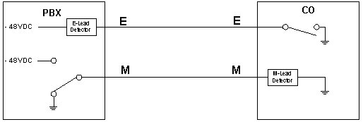
When a PBX call is established, the M lead is switched from ground to
–48VDC, The CO sees the –48VDC and sends a ground on the E lead to the PBX. A
ground over the E lead signals an incoming call from the CO (Figure 13).

E&M Type I Trunk, Idle Condition
Figure 13
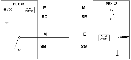
Unlike Type I, Type II uses two additional signal leads, Signal Ground
(SG) and Signal Battery (SB). These additional leads correct the common ground problems
associated with Type I. This configuration was developed for electronic PBX systems so
they will be more reliable and less noisy. It also works very well when connecting PBX to
PBX. Figure 14 shows the four signal leads, one pair for E, and one pair for M. Notice how
the E and SG leads of PBX #1 are connected to the M and SB leads of PBX #2 and visa versa.

E&M Type II Trunk, Idle Condition
Figure 14
To signal offhook, the calling system closes its M contact. The other
end detects the loop current and attaches digit detection equipment and signals the other
end by using either Wink Start, Delay Dial or Immediate Start (discussed later in this
text). Some systems send dial tone in addition to the signaling. The calling system sends
its digits. The called system routes the call and rings the appropriate instrument. When
the instrument comes off hook, the called system closes its E contact.
Either end may disconnect by opening its respective contact. The other end senses the open and opens its contact.
Direct Inward Dial
Many companies desire to allow callers to reach their system users directly, without the assistance of an attendant or voice processing system. In the early days of telephony, the only way to do this was to dedicate one line or trunk to each user. The problem with that is that it can become very expensive. Direct Inward Dialing (DID) solves this problem. Calls to a DID originate from a public CO and terminate on a PBX station instrument. Traditionally, DIDs were incoming only, but today they may also be used for outgoing calls (two-way DID).
A DID customer purchases a block of numbers from the local CO. For the sake of this text, 555-1000 through 555-1099, a block of one hundred numbers. The customer, depending on their DID traffic will have for instance, a block of only 25 DID trunks installed.
When an outside caller dials 555-1120, the CO chooses an idle trunk in the block of 25 trunks and signals the PBX that it has a call, using Wink Start, Delay Dialing or Immediate Start, Depending on the design of the trunk. When the PBX responds appropriately, the CO sends the digits 1020. The PBX detects the digits and routes the call to the telephone programmed as extension 1020, ringing the instrument. The number of digits sent may vary depending on the service and system that a customer uses. Once the quantity of digits is determined, during circuit design the CO will always send the same quantity of digits.
This arrangement allows the customer to share many numbers over just a few trunks, thus affording them a substantial savings on trunks.
Many times, the customer will not use all the numbers assigned to them.
The FCC requires those unused DID numbers to be answered and/or identified in some way.
Depending on the PBX, the unassigned numbers may be routed to a variety of places, such as
the attendant or a recorded announcement.
In order for a system to receive digits, it must be able to detect digits. Either DTMF, Dial Pulse or in some cases Multifrequency (usually used between COs and internationally). It is not cost effective to provide this equipment for each and every trunk. Especially when a trunk only uses the circuit for a relatively short period of time. This is why CO and PBX trunks share a small number of these circuits. Attaching the digit detection equipment to a trunk only during the short time they are needed.
PBXs and COs signal the distant end when the digit detection equipment
is ready. Using either signaling schemes or sending dial tone, as described above. In
addition to these schemes already discussed, there are several other methods available for
signaling between two switching systems, Delay Dial, Wink Start and Immediate Start.
A system using Delay Dial signals the calling system by going off hook
during the time it is attaching the digit detection equipment. When the equipment is ready
the called system goes back on hook. The time duration between offhook and onhook is the
delay before dialing. The calling switch sees the delay as a signal that it may dial. When
the digits are received, the called system routes the call and rings the appropriate
instrument. As soon as the instrument goes offhook, the called system goes offhook on the
trunk. Both ends stay off hook for the duration of the call. Either end going back onhook
accomplishes disconnection. As with any signaling method, both ends must be programmed for
the same signaling scheme.
Wink start is very similar to Delay Dial except that the called system
attaches the digit detection equipment first and then goes offhook for about 250
milliseconds and then back onhook (Wink). After the Wink, the calling system dials. When
the digits are received, the called system routes the call and rings the appropriate
instrument. As soon as the instrument goes offhook, the called system goes offhook on the
trunk. Both systems stay offhook for the whole duration of the call. Either end going back
onhook accomplishes disconnection.
A Trunk using Immediate Start sends an offhook - onhook wink on
incoming calls, the same as Wink Start. Outgoing calls are handled differently. The PBX
seizes the trunk and starts a timer (300 to 500 milliseconds). Digits are sent either
after seeing a wink from the far end or after the timer has expired, whichever comes
first.
Wink Start, Immediate Start and Dial Delay must have a method of returning a busy condition to the calling system. This is needed when the instrument that the call is routed to is busy. Most systems will send a series of flashes back to the calling system at the rate of a fast busy. The calling system recognizes this, drops the trunk and sends a fast busy tone (also known as a reorder tone) to the originating instrument.