CS1000E Rls. 7.5 Installation
10. Add virtual trunks
Avaya suggests there is no reason for administrators to access the CS1000 CLI except for troubleshooting and disaster recovery. Therefore, we're going to do the next steps purly from within Element Manager, and in the process, try to get familiar with the EM command layout and menu structure.
Perform initial ESN block configuration:
Navigate to Dialing and Numbering Plans/Electronic Switched Network.
Inside the Network Control & Services section:
- Click on Network Control Parameters (NCTL)
- Nothing needs to be checked on the initial screen. Click Submit.
- Click on Network Control Parameters (NCTL) again.
- Now the options exist to associate NCOS 0 through 7 with the relevant FRL. If needed build more. Clicking the NCOS hyperlink shows how it's configured. Click Edit, to make changes. Set NCOS 0 to FRL 0, NCOS 1 to FRL 1 and so on through NCOS 7. For a typical configuration, nothing but the FRL needs to be changed. Click Submit to save changes for each NCOS.

Click on ESN Access Codes and Basic Parameters.
- In the General Properties section:
- Set the NARS/BARS Access Code 1: to 9, or other number as determined in the installation plan.
- Set the NARS Access Code 2: if needed.
- Set Maximum number of Steering Codes: to 20. This is just a recommendation. Set a higher number if needed.
- Set the Number of digits in CDP DN to 4.
- In the Limits Section
- Set the first eight entries to 20. Leave the last entry blank.
- Click Submit.
Modify the CDB to allow use of ISDN trunks:
Navigate to Customers.
- Under Customer Number, click 00.
- Click ISDN and ESN Networking.
Under General Properties:
- Change Flexible trunk to trunk connection option: to Connections only.
- Under options: select both Transfer on ringing of supervised external trunks, and Connection of supervised external trunks.
- Select Network option: Coordinated dialing plan routing.
- Select Integrated services digital network.
- Click Save.
Click once again on ISDN and ESN Networking. Under Calling Line Identification:
- Click Calling Line Identification Entries.
- Under Calling Line Identification Entries, click Add... A popup box will state CPND must be configured. Click OK.
- Configuration: should be Standalone.
- Change Maximum length: to 27.
- Change Default length: to 27.
- Check the box next to Display reasons for call redirection:
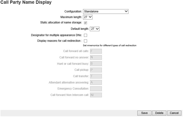
- Click Save. This brings up the New Calling Line Identification screen.
Here, CLID table 0 is built to have the system send out the customers published number, rather than an individual caller's DN. - Set the Local Code: to the customer's published number.
- Change Use DN as DID: to NO.
- Click Save.
Add virtual loop:
Navigate to System/Core Equipment/Superloops.
- Click Add...
- Set Superloop: dropdown box to 200 or whatever number fits the installation plan.
- Change Superloop type: to Virtual.
- Click Save.
Add a D-Channel:
Navigate to Routes and Trunks/D-Channels.
- A popup box states there are no D-Channels configured. Click OK to add one.
- Use dropdown box to select DCH Number: 200, then click to Add.

- Set the D Channel Card Type: to DCIP.
- Set the Country: to NET.
- Set the Interface type for D-channel: to SL1.
- Set the D-Channel PRI loop number: to 200.
- Click Submit.
Add the VTRK routes:
Navigate to Routes and Trunks/Routes and Trunks.
- Click Add route.
- Set the Route number (ROUT): to 200, or whatever number fits the installation plan.
- Set the Trunk type (TKTP): to TIE
- Set the Incoming and outgoing trunk (ICOG): to IAO.
- Set the Access code for the trunk route (ACOD): to some number that fits the installation plan.
- Check the box next to The route is for a virtual trunk route (VTRK):
- Set the Zone for codec selection and bandwidth management (ZONE): to 10.
- Set the Node ID of signaling server of this route (NODE): to the Node ID used when the node was built.
- Set Protocol ID for the route (PCID): to H323. If there are both H323 and SIP trunks in the system, build a second route for the SIP trunks identical to this route but respond with SIP for this entry.
- Check the box next to Integrated services digital network option (ISDN):
- Change the Mode of operation (MODE): to ISLD.
- Set the DCH number (DCH): to 200, or whatever virtual loop you built.
- Set the Interface type for route (IFC): to SL1.
- Change the PNI (Private Network Indicator) to 1.
- Click Save.
Add virtual trunks:
Next to the route click Add Trunk.
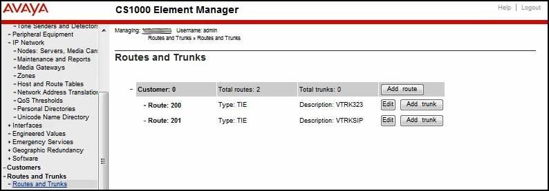
Under Basic Configuration:
- The Multiple trunk input number: dropdown box will change to an entry that must be filled in as soon as the Trunk data block:, next item, is changed to IPTI.
- For Trunk data block: choose IPTI.
- Go back to the Multiple trunk input number: and enter how many trunks to build.
- Enter a Terminal number: in large system, l s c u format.
- Set Member number: to 1 if this is the first trunk being added to the route.
- Set the two entries, Start arrangement Incoming: and Outgoing: to IMM.
- Set a TGAR.
- Set a Channel ID for this trunk: to 1 if this is the first trunk being built on this DCH.
- For Class of Service: click Edit.
- Set Dial Pulse: to DTN.
- Set Restriction level: to UNR.
- Click Return Class of Service.
Under Advanced Trunk Configurations:
- Set the Network Class of Service group for these trunks to whatever NCOS fits the installation plan.
- Click Save.
One DCIP DCH works for both SIP and H.323 virtual trunks. The DCH assigns the appropriate channel for the call by using a Channel ID (CHID). For this reason the CHID must be unique regardless of which route the trunk is in. Using the example above, if the H.323 trunks are built first, and 30 are built, the CHID of the first SIP trunk must be 31. If there are 10 SIP trunks they will have CHIDs 31 through 40. If later additional H.323 trunks are added to the system, the first additional trunk will have CHID 41.
Check to see that the virtual trunks are registered. From LD 117 a STAT SERV will tell you if there are any virtual trunks registered. In LD 96 the command STAT DCH will tell you if the DCH is active and established. Via EM you can see the virtual trunks with the vtrkShow command. Also in EM you can see the DCH status from two places, System/Maintenance and Routes and Trunks/D-Channels.
Stat virtual trunks via EM:
From System/IP Network/Maintenance and Reports click GEN CMD.
From Group choose Vtrk.
From Command choose vtrkShow.
In the Protocol field enter h323 or sip.
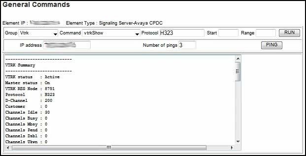
In the VTRK Summary look for VTRK status : Active, Master status : On, Channels Idle : 10, or whatever number of channels exist.
Stat D-Channels via EM:
From Routes and Trunks/D-Channels click D-Channel Diagnostics (LD96).
Click Submit on the first line, Status for D-Channel (STAT DCH).

Add the MG Conference and TDS loops:
Each Media Gateway (MGC) requires a Conference (MGCONF) and TDS (MGTDS) loop.
Navigate to System/Core Equipment/Loops.
- Using the dropdown box, choose Tone and Digit Switch and click Add...
- Enter the TDS loop number: using the following guidelines: Start counting by two's with 100 for loop 0 shelf 0. In the example 4 0 is being added, which works out to loop 104.
- In the IP media gateway: box, enter the loop and shelf.
- Click Save.
Back on the Loops page, use the dropdown box to select MG
- Conference then click Add...
- Conference loop numbers start with 101 for shelf 0 0. Enter the loop number in the Conference loop number: box.
- Enter the shelf information in the IP media gateway: box.
- Click Save.
Note in the image below that the new loops come up disabled.
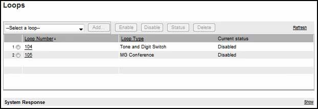
To enable the TDS loops, navigate to System/Maintenance.
- Select LD 34 - Tone and Digit Switch.
- Use the Loop Commands dropdown box to choose ENLL – Enable tone and digit loop.
- Under Command Parameters enter the loop #, not the MG loop shelf.
- Under Action click Submit. In the field below you'll see the command with OK in response.
Follow the same procedures for LD 38 - Conference Circuit. After the Conference loop is built, navigate back to the loop page and see that both have a Current status of Enabled.
To print, PRT CEQU in LD 22. MG Conference and TDS loops can be built on any loop, for example:
MGTDS        IPMG  IPMG_TYPE
         100  000  0   MGC
         102  000  1   MGC
         104  004  0   MGC
         106  004  1   MGC
         108  008  0   MGC
         110  008  1   MGC
MGCONF       IPMG  PORTS  IPMG_TYPE
         101  000  0   30    MGC
         103  000  1   30    MGC
         105  004  0   30    MGC
         107  004  1   30    MGC
         109  008  0   30    MGC
         111  008  1   30    MGC
Add Digitone Receivers:
Each Media Gateway (MGC) requires eight (8) Digitone Receivers (DTRs) built on virtual card 15.
Navigate to System/Core Equipment/Tone Senders and Detectors.
- On the next screen click the Digitone Receivers link.
- On the Digitone Receivers page click Add...
- On the New Digitone Receivers page enter the starting Terminal Number, e.g., 004 0 15 0.
- At the Number of Digitone Receivers: dropdown box choose 8.
- Back on the Digitone Receivers page click the Maintenance Commands link.
- Use the Loop Commands dropdown box to choose STAT - Get status TDS loop.
- Under Command Parameters, enter the loop shelf of the MG you want to stat. The output should show 0 disabled.
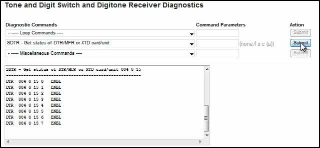
- Alternatively you can use the Card and Unit Commands dropdown box to choose SDTR - Get status of DTR/MFR or XTD card/unit.
- Enter the loop shelf card in the Command Parameters box. The output should show all units enabled.
