CS1000E Rls. 7.5 Installation
7. Element Manager - Add node and configure SS
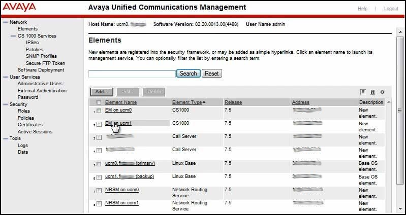
Element Manager (EM) is used for the next few configuration steps. EM has changed substantially from the earlier versions. There is also a new section for station administration, accessible from the Phones link on the left of the main page, which allows the same level of user administration as MAT/OTM/TM. However, this section focuses on adding and configuring the node.
No information is actually stored in Element Manager. It's a browser interface used to retrieve and configure the CS1000 and its node properties. For this reason Element Manager on either Linux server can be accessed for administration and maintenance.

Add the node:
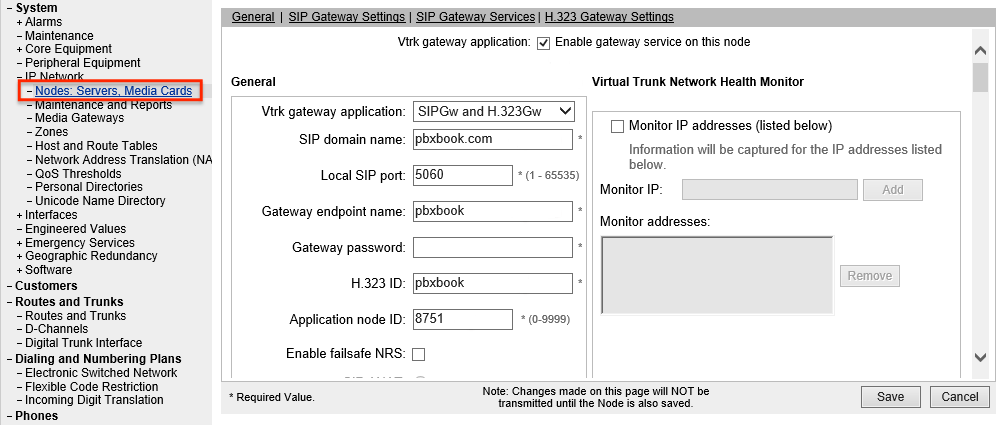
Navigate to IP Network/Nodes: Servers, Media Cards and click Add...
Step 1) Define your node and its services
- Node ID = Last digit of the subnet's second octet and the whole third octet. If the total is only three digits, add 1 at the end.
- ELAN Gateway IP address: Enter the GW and confirm the subnet mask is preconfigured correctly.
- Node IP is your TLAN subnet with a host address. Check this subnet mask and make corrections if needed.
- Applications: Select the following:
UNIStim LTPS
Virtual Trunk Gateway
Personal Directory - Click Next.
Step 2) Associate Signaling Servers
- Use the drop down box to choose a signaling server and click Add... Repeat until all signaling servers required in this network have been added.
- Select one of the signaling servers as the leader by checking the box next to it on the left and Make Leader. Leader assignment is reflected Role column at the far right of the screen.
- Click Next.

Step 3) UNIStim LTPS Configuration Details
- Scroll down to Network Connect Server.
Enter TLAN IP addresses of the Network Connect Servers. Use the TLAN IPs of the signaling servers you selected in the previous screen, with the Leader SS as the primary NCS.
Assign an H.323 ID: - Click Next.
Step 4) VTRK Gateway Configuration Details. There are a lot of configuration options on this screen. The following skips most entries, leaving them at default. The configuration changes below will get the system running with basic features and capabilities.
- General
Vtrk gateway application: Use the dropdown box to choose SIPGw and H.323Gw if that is what the keycodes include.
SIP domain name: your system's domain name e.g., pbxbook.com
Gateway endpoint name: Provide a simple, intuitive name.
Gateway password: provide a password you will not forget. WRITE IT DOWN!
H.323 ID: Use the H.323 ID you used in the previous screen.
Application node ID: Enter the node ID.
- SIP Gateway Settings
- Set the Proxy Or Redirect Server: Proxy Server Route 1: Primary TLAN IP address: to the Primary NRS's TLAN IP address.
- Set the Proxy Server Route 2: Primary TLAN IP address to the Alternate NRS's TLAN IP address.
- Remove any 0.0.0.0 strings that remain in this section. - SIP Gateway Services
Uncheck SIP Converged Desktop
- H.323 Gateway Settings
Set the primary gateway to your Primary NRS's TLAN IP address and the alternate as the Alternate NRS's TLAN IP address. - Click Next
- Navigate through the Personal Directory screen, ensuring it's enabled, then click Next.
- Look over the information then click Finish.
- On the Node Saved screen, click Transfer Now...
- On the next screen select both signaling servers and click Start Sync. The right-most column, Synchronization Status will show Sync required until the sync is successfully completed, at which time it will show Synchronized.

- Select both signaling servers and click Restart Applications.
If a TTY has USER MTC the output will show when the two signaling servers' ELAN hosts are enabled. This is when they register their pbxLink. Once this appears on the screen, from LD 117 issue the command STAT SERV to confirm the PBXLINK STATE for each SS is LINK UP and that the correct SS holds the position of leader.
The signaling servers don't install completely configured. For most installations default settings will work fine. For times when a more compressed codec is required additional configuration changes are needed. Additional information on zones and codec use is discussed below. The following steps will leave the node ready to support VoIP connections across a lower speed WAN.
Add G.729 codec support to the node:
From IP Network/Nodes, Servers, Media Cards click the Node ID link.
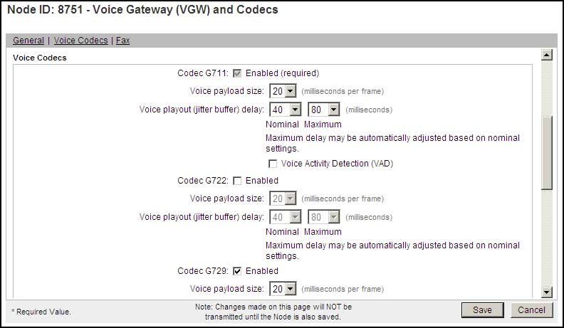
In the top section of the window scroll down and select Voice Gateway (VGW) and Codecs.
In the General section ensure the following are checked:
- DTMF tone detection
- Modem/Fax pass-through
- V.21 Fax tone detection
Scroll down to the Voice Codecs section and ensure G.711 and G.729 are selected. G.729 probably needs to be added.
Click Save.

On the Node Details screen, click Save.
On the Node Saved screen, click Transfer Now...
On the next screen select both signaling servers and click Start Sync.
Click Restart Applications