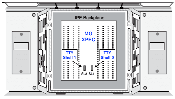
MG XPEC TTY Ports
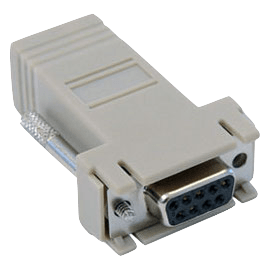
Within the MG XPEC cable kit (NTDW25AAE6), two cables (NTDW26ABE6) are provided - blue cables in the pictures below. These cables are used to connect the MG XPEC TTY ports (from SL1 and SL3) to RJ45 couplers in the I/O panel. From these couplers, make a connection to a PC/Mac running terminal software using a standard network cable and one of the adapters provided, eg: RJ45 to DB9.
Two kinds of RJ45 adapters are included in the cable kit:

- RJ45 to DB9: to connect to DTE devices, eg: PC/Mac serial port
- RJ45 to DB25: to connect to DCE devices, eg: a modem
The default TTY settings are: 9600, 8 none 1 - see Using PuTTY for Serial.
Serial Data Pin Descriptions:
| RJ-45 Pin # | MG XPEC Signal | DB-25 Pin # | DB-9 Pin # | Description |
|---|---|---|---|---|
| 1 | nc | 6 | 6 | Data Set Ready (in) |
| 2 | DCD | 8 | 1 | Data Carrier Detect (in) |
| 3 | 12V | 20 | 4 | Data Terminal Ready (out) |
| 4 | GND | 7 | 5 | Ground |
| 5 | RXD | 3 | 2 | Receive Data (in) |
| 6 | TXD | 2 | 3 | Transmitted Data (out) |
| 7 | nc | 5 | 8 | Clear To Send (in) |
| 8 | 12V | 4 | 7 | Request To Send (out) |
Adapter pinouts:
- The N0211605 DB9 Null Modem adapter (supplied in cable kit) is used with a standard network cable to connect to DTE devices.
- The RJ45 to RJ45 MRV adapter cable is required to use the (newer) NTDW26ABE6 cable with a MRV terminal server. The original NTDW26AAE6 does not require this cable (see below).
Connecting the cables:
Connect a NTDW26ABE6 cable between the IPE shelf rear SL1 / SL3 connectors and I/O panel RJ45 couplers, observing the correct connector orientation: make sure UP! is up! Do not touch any pins on the IPE back plane, they will zap you if the shelf is powered up!
Each cable provides access to TTY 0 and TTY1 for half of the MGXpec. As you look from behind, the right side is the even: shelf 0 (SL1) and the left side is the odd: shelf 1 (SL3). Both MGXPec halves are independant, and must be individually configured. If you can only find one cable, carefully move it as required to configure the card sides.
For configuration see MGC Card Settings and mgcsetup. An MGX has a fixed DB96 DSP daughterboard (each half).

Difference between NTDW26AAE6 and NTDW26ABE6:
- NTDW26ABE6 is an updated version of the MG XPEC TTY cable, with a pinout changed to match the MG1010 serial ports.
- NTDW26AAE6 is the original version of the MG XPEC TTY cable, designed to match the MRV terminal server serial ports.
| RJ-45 Pin # | NTDW26ABE6 Signal | NTDW26AAE6 Signal |
|---|---|---|
| 1 | nc | 12V |
| 2 | DCD | DCD |
| 3 | 12V | RXD |
| 4 | GND | GND |
| 5 | RXD | GND |
| 6 | TXD | TXD |
| 7 | nc | 12V |
| 8 | 12V | nc |
supplied with the MG XPEC cable kit and MG1010 cabinet,
for local TTY port access from a terminal or PC/Mac.

Add MG XPEC TTY ports to CS1000:
You can add MG XPEC TTY port(s) to the CS1000 and assign a function such as maintenance (sch mtc bug) or CDR (cty).
> ld 17
REQ chg
TYPE adan
ADAN chg tty xx                   xx = new XSM port
CTYP mgx
IPMG sl s                         sl = super loop, s = shelf
PORT x                            x = tty port 0 or 1 on MGXPEC
DES xxx                           xxx = designator
BPS
BITL
STOP
PARY
FLOW
USER xxx                          xxx = sch mtc bug, or cty
TTYLOG
BANR

MEM AVAIL: (U/P): 94556775 USED U P: 9063402 32172 TOT: 103652349
DISK SPACE NEEDED: 32 KBYTES.............
Print ADAN in LD 22, STAT TTY in LD 37.
Add XSM port to CS1000, if required:
Optional step, skip if an Extended System Monitor port is not required.
A third TTY port is available for the system monitor. It requires an NTDW26BAE6 XSM cable, connected to the SL0 connector.
> ld 17
REQ chg
TYPE adan
ADAN chg tty xx                   xx = new XSM port
CTYP xsm
IPMG sl s                         sl = super loop, s = shelf
DNUM xx                           xx = device number
DES XSM


