4000 Series Stacking
You can connect up to eight 4000 Series switches in a stack to provide up to 400 ports. The stack is managed as a single unit.
Steps:

- Upgrade all the switches to the same firmware release.
- Set the rear Unit Select switch to Base on ONE UNIT ONLY (eg, top).
- Connect the stack using the Cascade DOWN / UP cables.
- Loop the last unit back up to the Base unit to make a ring.
Only one switch in a stack can be the base unit; ie, with the Unit Select switch in the right 'Base' position. All other switches must have the Unit Select switch in the left position. The base unit designation for a switch appears on the front panel LED display.
You can build either a Cascade Down, or Cascade Up configuration, depending on the stack cabling arrangement. Avaya recommends a Cascade Down (stack down) configuration, although either configuration is functionally identical to the other.
The following guidelines apply to stack configuration:
- A stack is a single logical unit. The ports are numbered 1/1, 1/2... 2/1, 2/2... 3/1, 3/2... etc.
- If a unit fails, or if a cable is accidentally disconnected, other units in the stack remain operational.
- The console port of any switch in the stack can be used to establish a console connection.
- You can manage the stack via Telnet or Web Interface, through any stack switch port.
- When you stack two or more switches, use the 3-foot cascade max-return cable (AL4518002-E6)
Setting IP parameters
- Connect a serial TTY to a front panel Console port: 9600 8-N-1
- Type Ctrl-y to activate a session, followed by
enable - Enter the
configure terminalcommand. - Enter the
ip addresscommand to set the switch or stack IP address. Command syntax:ip address [stack | switch] <ip address> [netmask <subnet mask>] [default-gateway <gateway address>]Use the 'stack' keyword to set the stack IP address, eg:
stack ip address 10.10.10.100
The switch IP address applies ONLY when the switch is not stacked, and can be omitted.
The restore factory-default command resets the switch or stack to its default configuration. When the switch is set to factory default parameters, the CLI Quickstart appears which enables you to set default IP information.
LED indicators
BASE should be green on the base unit. The UP/DOWN LED's of all units should be green. Amber or no LED indicates a problem.
Use commands show stack-info, and blink-leds unit <1-8> to identify a stack unit by blinking its LEDs.
See 4000 Series LED indicators.
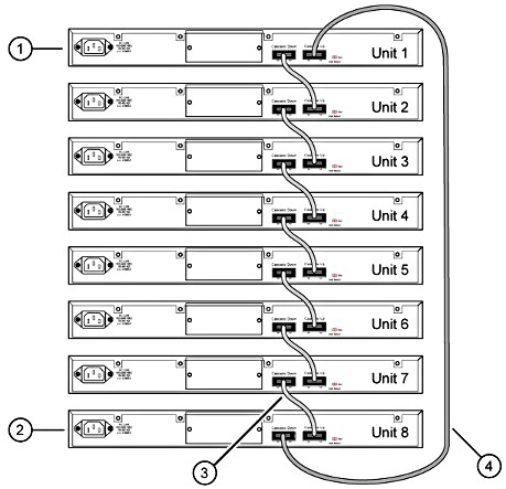
Cascade Down
The base unit is located at the top of the stack. The Cascade Down connector of the base unit terminates in the Cascade Up connector on the next unit in the stack, and so on. The unit order is 1, 2, 3.... from the top down. The bottom unit loops up to unit 1.
|
Cascade Down (Stack Down) Configuration:
Stacking 2 switches, connect: |
 |
Cascade Up
The base unit is located at the bottom of the stack. The Cascade Up connector of the base unit terminates in the Cascade Down connector on the next unit in the stack, and so on. The unit order is 1, 2, 3.... from the bottom up. The top unit loops down to unit 1.