Controllers and Segments

The image right is a NT8D01 controller card. It's installed in each IPE shelf between slots 7 and 8, and interfaces upto 4 Superloops to an IPE module.
See also Network Loop Configurations and Superloops / Controllers.
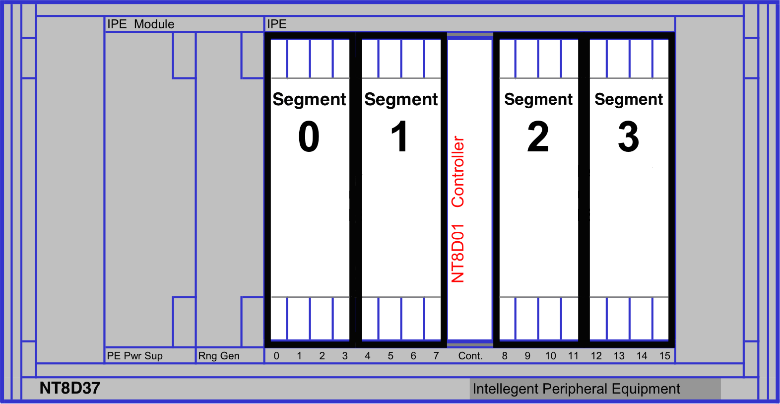
An NT8D37 IPE Module is divided into four segments of four card slots, numbered 0-3. Segment 0 consists of slots 0-3, segment 1 consists of slots 4-7, segment 2 consists of slots 8-11, and segment 3 consists of slots 12-15. A superloop can be assigned from one to eight IPE segments.
IPE Module with four segments:
To print the relationship between
Superloops and controllers...
Go to LD 97, and print the superloops (SUPL) and the controllers (XPE).
You will see all controllers and which Superloops are assigned to them.
Print the superloops:
REQ: prt
TYPE: supl
SUPL: <hit return to show all>

SUPL  SUPT SLOT XPEC0   XPEC1

 004  STD  LEFT 01 0 3  02 0 3
 024  STD  LEFT 03 0 3  -- - -
 100  ---- ---- PHANTOM -- - -
 148  ---- ---- VIRTUAL -- - -
Print the controllers:
REQ: prt
TYPE: xpe
XPEC: <hit return to show all>

 S0  S1  S2  S3  LOC     DIS RGTP

 01 004 004 004 004       NO  08
 02 004 004 004 004       NO  08
 03 024 024 024 024       NO  08
An IPE module (shelf) is split into 4 segments. A superloop can service from 1 to 8 segments. The controller is the IPE card between slots 7 and 8. In this example, the controller faceplate display would alternate between C0 and either 01, 02 or 03 depending on which IPE shelf you're looking at: this is its "controller number", and is related to the SUPL assigned to that controller. In this example:
- Loop 4, Shelf 0 = Controller 01, segments 0 to 3 (XPEC 0)
- Loop 4, Shelf 1 = Controller 02, segments 0 to 3 (XPEC 1)
- Loop 24, Shelf 0 = Controller 03, segments 0 to 3 (XPEC 0)