Adding an IPE shelf
1With a DC system, you don't have to power down the column IF you're careful, but do ensure the shelf breaker is off! DC columns have 5 individual breakers in the base, one for the blower, BLO, and one for each module: CB0 thru CB3.
2With a DC system, while checking the breakers, also check that the module power input is wired:
- Modules 0 and 1 connect to BAT/RTN 0,1: CB0, CB1
- Modules 2 and 3 connect to BAT/RTN 2,3: CB2, CB3
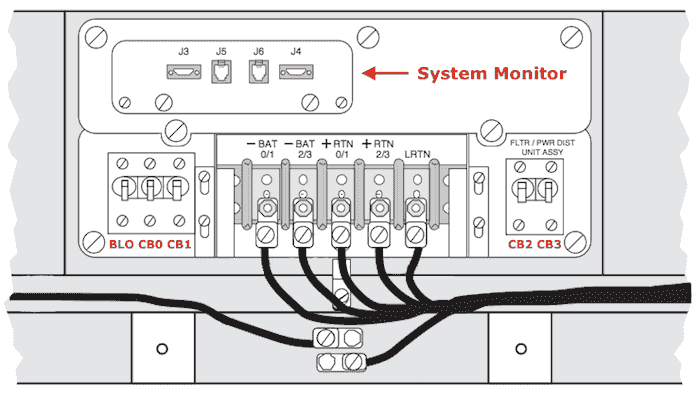
3If the column houses the Master System Monitor, find the System Monitor TTY in ADAN (with XSM=yes), and disable it in LD 37: DIS TTY x
4Unseat the System Monitor from the column base, to stop it tripping the breakers when you remove the top cap. You just need to pull it forward a bit.
5Carefully remove the column top cap - this has the temperature sensors on it - be careful with the ribbon cable. If you didn't power down the column, removing the top cap will make the base tray fans ramp up (due to a perceived "over temperature").
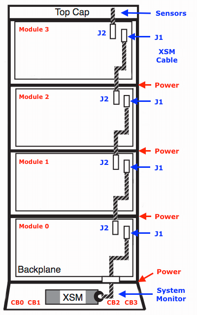
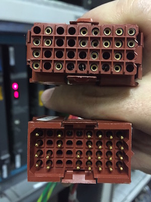
6Drop in the new IPE shelf, and connect the power and system monitor cables. The XSM cable comes from J2 of the previous shelf, and plugs into J1 of the next shelf. It runs from the pedestal to the top cap. The rectangular power plug is keyed with two cut corners at one end (left) and a zig-zag at the other, so check the connector orientation and make sure you're lined up. The cables can be fiddly, so take your time. Below, the power connectors.
7Replace the top cap, and connect the XSM Ribbon Cable.
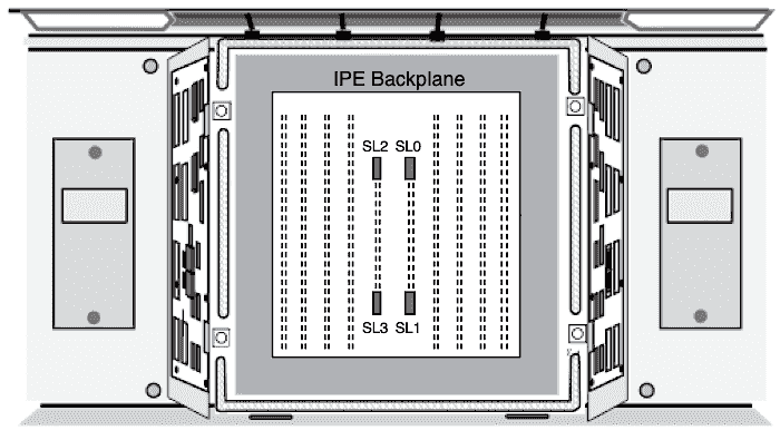
8Identify a vacant super loop slot. The picture below gives an idea where: the physical slot is the superloop number, use the bottom SL connector (J2) on the NT8D04. Make sure the NT8D04 Enable/Disable switch is disabled before inserting.
Refer to Group, Shelf, Slots and Loops to help identify physical loop and slot numbers.
A network card arrangement example:
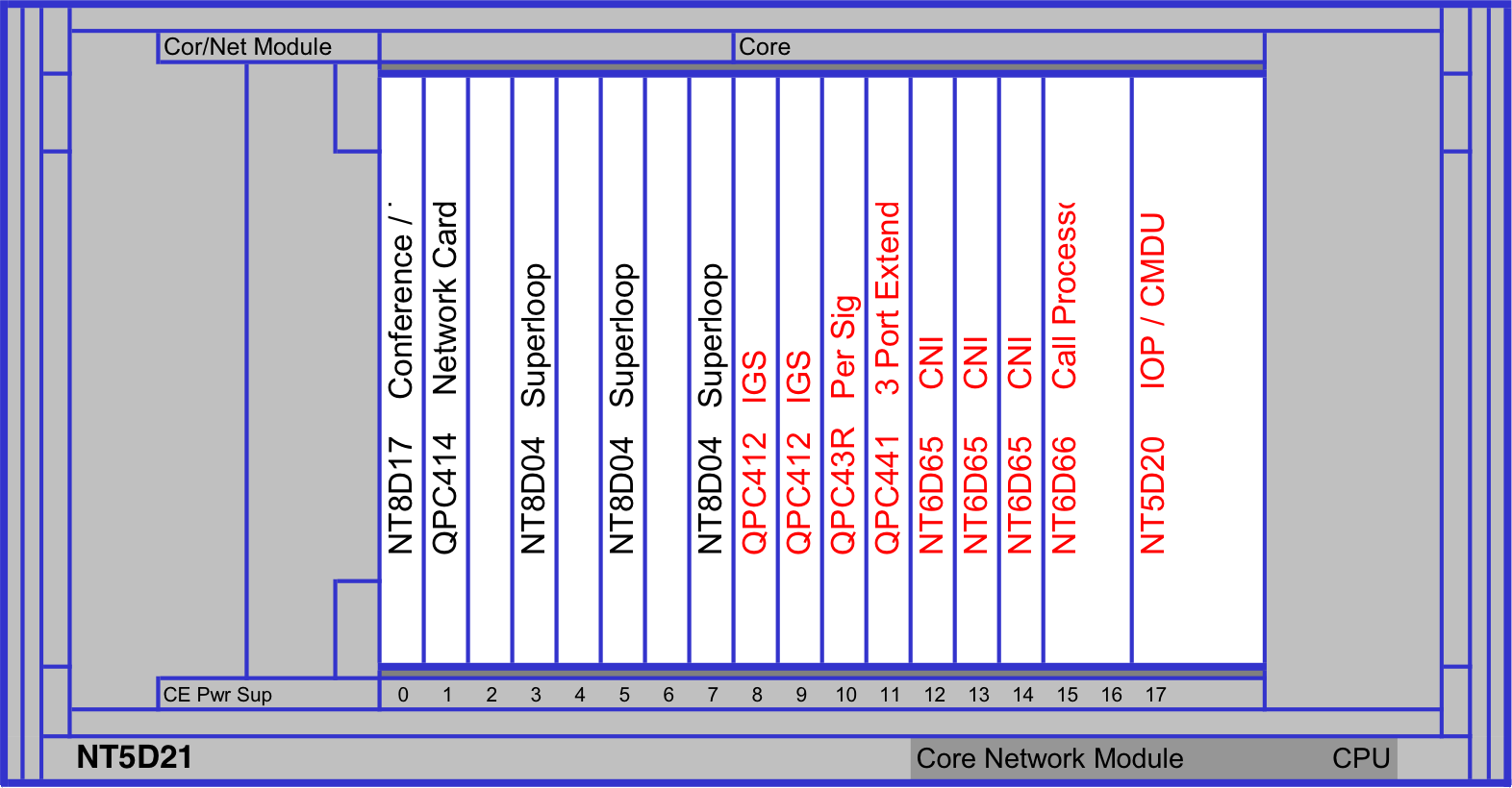
An NT8D04 may be placed in a Left (even) or Right (odd) slot (0-7). This is specified when defining the Superloop in LD 97. Regardless of the slot, Superloop numbers are always even and in multiples of 4. Eg, an NT8D04 in slot 3 is still Superloop 4.
9Run the XNET I/O Cable (NT8D88AD) to the back of your new IPE - plug it in to the rear SL0 position. Pay attention to the connector orientation! The connector is NOT keyed, but marked with the UP↑ direction.
Note: Do not 'enable' the NT8D04 Enable/Disable switch before the superloop cabling is in place.
After the hardware is side is completed, continue with the software configuration.
10In LD 97, add your new controller:
REQ chg
TYPE xpe
XPEC x          Where: x is the next controller number
LOC             IPE shelf location description
RGTP x          Where: x is the Ring generator type, 8 or 16. 8 is default
Note: Common equipment is always 'changed', therefore CHG, not NEW.
11In LD 97, add your new superloop:
REQ chg
TYPE supl
SUPL x          Superloop number, in multiples of 4
SLOT L or R     Left or Right network shelf card slot, probably left
SUPT <cr>       Superloop type: the default is STD, and what you require
XPE0 x y z      Where: x=controller defined above, y=start segment z=end segment
                eg, 5 0 3 - controller 5 for the whole shelf (all 4 segments)
XPE1 <cr>       Only required if you are segmenting the shelf
Note: if you are adding a shelf 1 to an existing NT8D04 (because you've run out of SL slots), use the cards top connector (J1) for the DS30 cable, and add an XPE1 to the loop. At the IPE end it will still connect to SL0. The time slots will then be split between shelves, eg, 120 timeslots to potentially 768 TN's. Do not do this with high traffic demands! See Network Loop Configurations.
12Set all the pedestal circuit breakers to ON. and turn on the new IPE shelf PWR supplies
13Carefully reseat the System Monitor, and enable its TTY (if disabled above) in LD 37: ENL TTY x.
Perform a LD 37: STAT XSM to make sure there are no PSU errors.
14Enable your new hardware in LD 32:
ENLL x- enable the superloop
ENXP x- enable the controler
15Perform a loop test in LD 30. If there is a problem, an NWS message is output:
SHLF l s - 'l s' are the loop and shelfIf it passes, add a Digital Line Card, and build some stations. You may have to upgrade the system limits (LD 22: PRT, SLT) with a new keycode to accommodate the extra slot capacity.