Load Signaling Servers (4.5)

The following applies to the NTDU27 "pizza box" signaling server. A 'Leader' server is always required, though two servers may be installed in a load-sharing redundant configuration (one leader and a follower) for higher reliability. A DB-9 serial port, and CD-ROM drive are located behind the front drop down cover.
Connect the server to ELAN and TLAN switch ports, TLAN is the UPPER connector.
Aside from power (100-240vac), no other rear connections are required.
NTDU27 Signaling Server Rear Panel:

Load 'Leader' Sig-Server
- Using a 9 pin serial cable, connect the server to a TTY. Set the rate to 19200 baud.
- Power-up the server, and put the Signalling Server Software CD in the CD drive.
- If the CD is recognised as a boot option, a menu will appear:
Read boot parameters from:

C: CDROM Drive
H: Hard Disk
 8 [H] c
- Press C to boot from the software installation CD. You should see:
Reading boot parameters from /cd0/nvram.sys - Wait until the Nortel splash screen appears, and press <CR> to continue.
- Press enter to partition the hard drive. You must do this. System will reboot.
- After the system has rebooted, follow instruction on the screen.
- Enter the Time and date: Day-month-year, and press Enter.
- Then test the hard disk (Press Enter). It may take up to 20 minutes. Finally, the Installation Menu will appear:
CS 1000 Signaling Server Software Install Tool (sse-4.50.25) ============================================================ M A I N M E N U The Install Tool will install Signaling Server software and related files. You will be prompted throughout the installation. Please enter: <CR> -> <a> - To perform a complete installation/upgrade (Signaling Server s/w, Internet Telephone f/w, Voice Gateway Media Card l/w, basic Signaling Server configuration). <b> - To install/upgrade Signaling Server software only. <c> - To copy Internet Telephone firmware only. <d> - To copy Voice Gateway Media Card loadware only. <e> - To perform basic Signaling Server configuration only. <t> - To go to the Tools Menu. <q> - Quit. Enter Choice> a - Press A or enter to perform a complete software installation.
- Then type yes. Installation may take up to 20 minutes, during which files are copied to the server.
- Press A to set the first Signal Server as Leader.
- Press A to set it as a CO-resident
- Press B (H.323 Gatekeeper only)
- Press A for Primary.
- Enter the Node ID
- Enter a host Name.
- Enter the ELAN IP, subnet mask, and Gateway IP addresses
- Enter the TLAN IP, subnet mask, and Gateway IP addresses
- Enter the Node IP address.
- Then the enter Call Server IP (Switch IP)
- Then press enter at NRS
A summary is displayed:
CS 1000 Signaling Server Software Install Tool (sse-4.50.25) ============================================================ You have entered the following parameters for this Leader SS : Node ID : 2870 Hostname : PBXBOOK_LDR ELAN IP : 10.10.10.15 ELAN address ELAN subnet mask : 255.255.255.0 ELAN gateway IP : 10.10.10.254 TLAN IP : 10.10.11.15 TLAN address TLAN subnet mask : 255.255.255.0 TLAN gateway IP : 10.10.11.254 Node IP : 10.10.11.17 NODE is always TLAN Call Server IP : 10.10.10.5 CS is always ELAN NRS configuration : Primary GK + SIP Primary NRS IP : 10.10.11.15 TLAN address Alternate NRS IP : 10.10.11.16 TLAN address Please enter: <CR> -> <y> - Yes, these parameters are correct. <n> - No, these parameters are not correct. Enter Choice> - Verify information entered, then type yes (or press enter).
- Verify the Signal Server is set as leader and press enter.
- Then press Q.
- Then choose quit and reboot. IMPORTANT! you must cleanly quit the installer program.
- Open Internet explorer, and enter the TLAN IP address. Element Manager should display.
Load 'Follower' Sig-Server
- As above, boot the signalling server from the software installation CD.
- Press enter to partition the hard drive. You must do this. System will reboot.
- After the system has rebooted follow the installation instructions on the screen.
- Then enter in Time and date. Day-month-year Press enter.
- Then test the hard disk (Press Enter). It may take up to 20 minutes.
- Press A or enter to perform a complete installation and upgrade.
- Then type y or enter. This may take up to 20 minutes, during which files are copied to the server.
Please enter: <CR> -> <a> - Set this Signaling Server as a Leader. <b> - Set this Signaling Server as a Follower. <q> - Quit. Enter Choice> b - Press B to set the second Signal Server as the follower.
- Type host name, example PBXBOOK_FLWR.
- Press enter again
- Then press Q.

- Then choose Quit and reboot (important).
Introduce the Follower to the Leader
Open Internet Explorer and bookmark Element Manager. Then login...
- User Id: admin1 / admin2
- Password: 0000
- Click on IP Telephony ► Configuration
- Click on node summary
- Click on the import node files
- Enter the leader signaling server's IP address
- Click on Import, then click Edit
- Go to the Signal Server 0.0.0.0 Properties
- Enter the Management LAN (ELAN) IP address

- Enter the Management LAN (ELAN) MAC address
(label lower right hand corner behind the front cover) - Enter the Voice LAN (TLAN) IP and Gateway IP address.
- Host name example; PBXBOOK_FLWR
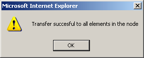
- Click Save and Transfer
- Click OK. The transfer process begins. It will fail - but don't worry!
- Press the Reset button to reboot the Media Gateway.
- Then click Save and Transfer again.