Vanguard E&M VoIP Tie Trunks
Installation Notes
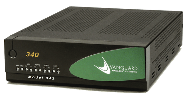
The following contains information to the successful installation of a VoIP tie circuit through a Vanguard 340E unit and an Option 11C. This information may be modified for use with other PBXs or VoIP tie units.
- Connector crimper with RJ-45 connectors
- punch-down tool
- voltmeter
- telephone butt set
- spudger for wire tracing
- BIX test clips
Vanguard Overview
A Vanguard 340E contains two dual-port voice daughter boards which are software
configured for use with E&M modules. The internal board strapping can be checked
against the Vanguard documentation for troubleshooting, however, this strapping should
already be pre-configured for installation. The cabling consists of power cord with power
supply, LAN crossover cable for connection to the VoIP circuit Router, and cat-5 cables with
RJ-45 connectors which provide connectivity to the Option 11C. The pins of each RJ-45 port
input MUST match the appropriate Option 11C wiring (see Table 1 below), with the exception
of Pin 1 which is Signal ground. These pins should be securely connected to the ground bar
of the Option 11C using Cat-5 or cross-connect wire, and should NOT be connected to the
Option 11C's board output.
Option 11C E&M Overview
- The Option 11C should be equipped with one or more E&M Trunk card(s) such as NT8D15AK, each with 4 trunk capacity.
- The Option 11C uses E&M signaling to communicate with the Vanguard.
- The E&M type most commonly used is 4-wire, Type 1.
- The E&M Trunk is programmed in LD 14, and must have STRI and STRO set to WNK (though IMM may be used).
- The VoIP Route is programmed in LD 16 and must have DLTN set to Yes (return courtesy dial tone).
- TGAR and TARG settings should match those used for analog E&M trunks.
Table 1 - Nortel to Vanguard Connections (E&M, 4-wire, Type 1)
| Option 11C E&M Port | Vanguard RJ-45 Pins |
|---|---|
| TA | T (Pin 6) |
| TB | R (Pin 5) |
| RA | T1 (Pin 4) |
| RB | R1 (Pin 3) |
| E | E (Pin 2) |
| M | M (Pin 7) |
| ECG | |
| ECSG | Ground (Pin 1), connect to PBX gnd |
Basic Process
- Install the Vanguard 340E, power up and connect to the VoIP circuit Router.
- Build cables to connect to Option 11C, cross-connect as needed (see Table 1).
- Change 11C trunk and route programming as necessary.
- A new route and trunk may be built to verify functionality before cutover.
- Verify Vanguard programming and perform diagnostics.
- Verify Tie functionality for both incoming and outgoing calls.
Troubleshooting - expect to need it!
- Tools useful for troubleshooting include a Voltmeter, a Telephone Butt Set, and the Nortel Maintenance Telephone feature (MTC class of service on a multi-line display phone).
- When the far end seizes a line, the E voltage should drop from approx. -48 volts to approx. -10 volts, indicating the line has been successfully seized.
- Check for solid ground PBX ground connection to Vanguard RJ-45 pin 1.
- From the PBX Maintenance Phone, access the specific trunk to be tested. On the BIX block, attach a Telephone Buttset to the RB/R1 and RB/T1 connections. If all connections are nominal and the trunks have been activated, you should be able to hear dial tone originating from the far end.
- If the circuit still does not respond, and the far end shows clean, check and double-check the wiring from PBX to Vanguard!!! Look for any cross-connect locations where the pins may have changed (e.g. USOC to 568A) - final feed to the Vanguard must match Table 1 above.


