Video Conferencing with BRI
This document was created to capture settings for the ISDN BRI connection for VTC and STE equipment. This setup is known to work on an 81C using the MISP (NT6D73) and SILC (NT6D70) cards to connect a Polycom VSX7000 system using four ISDN BRI lines (BRIL).
PART I
Basic Information for Installation
MISP and SILC cards are installed in specific locations in the switch. Use Steps 3 and 4 below for proper card placement in the switch. Pertinent information can be found in the Circuit Card: Description and Installation manual (553-3001-2211 3.0).
In preparation of installing the digital hardware, refer to the following information in order to guide you through the appropriate steps.
- Select the card slots where the ISDN BRI cards (MISP and SILC/UILC)will be located.
- Use LD 22 to print system configuration information and to identify unused network card slots.REQ PRT
TYPE CFN or CEQU- Use LD 20 to list unused IPE card slots to install SILCs, UILCs, and BRSCs.
REQ PRT
TYPE LUC
- Remove the module cover for card installation. - Refer to Page 22 of 126 Installing ISDN
BRI hardware (553-3001-218) Standard 3.00 August 2005 manual or pdf.
- Install the Multi-Purpose ISDN Signaling Processors (MISPs).
- For NT4N41 (Large Systems) - Network slots 0 - 7
- For NT8D35 (81C CPPII or CPPIV) - Network slots 5 - 12
- NOTE: MISPs cannot share network loop addresses with a Superloop Network Card in Large Systems. The MISP requires two network loops (BRI = 2 B-channels + 1 D-channel) and one network card slot. Installing cards in the Meridian will initially note the location (l s c) of the card slot being used.
- Install the S/T Interface Linecards (SILCs) and/or U Interface Linecards (UILCs) or
Basic Rate Signaling Concentrators (BRSCs) - All systems - IPE slots 0 - 15
- Connect ISDN BRI terminals. This procedure comprises the following:
- Connect the system to the Main Distribution Frame (MDF).
- Cross-connect the MDF.
- Connect ISDN BRI terminals to the DSL.
- Initialize the ISDN BRI terminals.
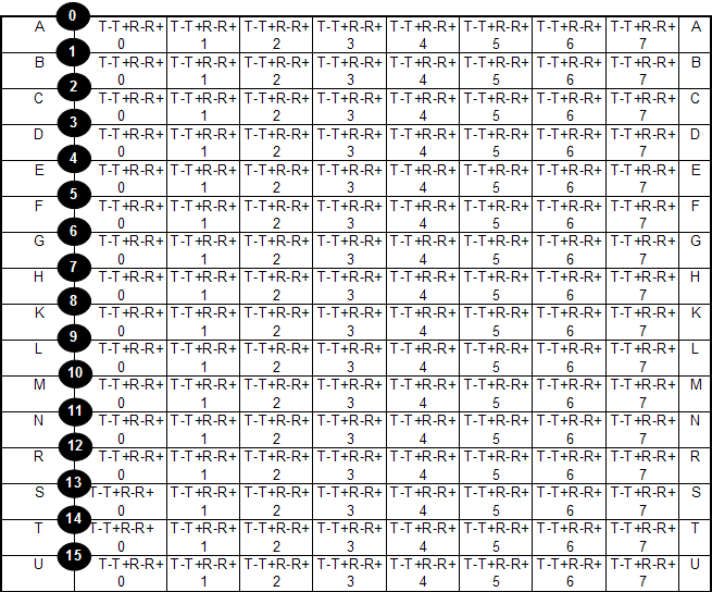
Figure 1: SILC port designations at the MDF - 16 port configuration
Based on the diagram above T-T+R-R+ represents two cable pairs wired 1, 2, 3, and 4 respectively. See Figure 2 for more details on this. Each letter represents the backplane connection at the PBX.
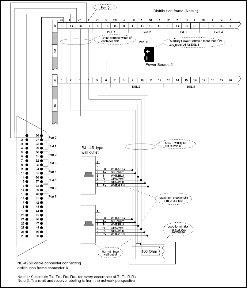
Figure 2: Cross-connect the SILC port office wiring
Assuming that the 25-pair cable coming from the SILC/UILC port is wired correctly, the first two pairs should be wired as follows (not including the power connections) for a RJ-45 connector using CAT5 from the block (MDF) to the ISDN device:
| First 2 Pairs | PIN | Second 2 Pairs |
|---|---|---|
| Wire 1 (white/blue) | pin 5 | Wire 1 (white/green) |
| Wire 2 (blue/white) | pin 4 | Wire 2 (green/white) |
| Wire 3 (white/orange) | pin 3 | Wire 3 (white/brown) |
| Wire 4 (orange/white) | pin 6 | Wire 4 (brown/white) |
Part II
Programming the Connection
The following information is a snapshot of programming use to set up the Polycom VSX7000. I was able to get the system and an ISDN handset up using the BRI connections from the PBX. First make sure you print your common equipment programmed in the PBX.
LD 22
Print Your Common Equipment
REQ  PRT
TYPE CEQU
CEQU
  MPED 8D
  TERM
  REMO
  TERD  018  019
  REMD
  TERQ
  REMQ
  SUPL 004 020 036 056
  SUPC
  SUPF
  DDCS
  DTCS
  XCT   000  016  032  048
  TDS  * 000 * 016 * 032 * 048
  CONF * 001 * 017 * 033 * 049
  MFSD * 000 * 016 * 032 * 048

  DLOP  NUM DCH FRM TMDI LCMT YALM TRSH
   TRK  060 11  ESF NO   B8S  FDL  00
  PRI2 010 011 040 041
       050 051
  APVL
  DTI2
  MISP  002 Specifies the loop # for the MISP
  SYNM 0
  EXT0  3PE
    CNI  009 000 000
    CNI  009 001 001
  EXT1  3PE
    CNI  009 000 000
    CNI  009 001 001
  MCFN  509 MB
LD 27
Program Your DSLs
REQ PRT
TYPE DSL
DSL  36 1 14 0 This setup uses 4 DSLs.  Each is printed below
DATE
PAGE
DES
NACT

TN   36 1 14 0
DES  VTC1
CUST 0
CTYP SILC
OPT  BRIL
MISP 2
MODE NTAS
B1CT VCE DTA B-Channel 1
B2CT VCE DTA B-Channel 2
LDN  NO
XLST 0
MTEI 20 This is defaulted to 8 for simultaneous calls.  You can leave at 8 if necessary
MCAL 16
MTSP 8
LAPD 0
PRID 2 Specifies an ETSI connection
PDCA 1
FDN
EFD
HUNT
EHT
TGAR 11 Specifies the restrictions to be placed on the line. Use your post settings
NCOS 5  Specifies the restrictions placed on network access. Use your post settings
SGRP 0
CAC_MFC 0
CLS  UNR ICDD CDMD MRD UDI ABDD PGND  BRTD
DATE 17 OCT 2007

REQ  PRT
TYPE DSL
DSL  36 1 14 1
DATE
PAGE
DES
NACT

TN   36 1 14 1
DES  VTC2
CUST 0
CTYP SILC
OPT  BRIL
MISP 2
MODE NTAS
B1CT VCE DTA
B2CT VCE DTA
LDN  NO
XLST 0
MTEI 20
MCAL 16
MTSP 8
LAPD 0
PRID 2
PDCA 1
FDN
EFD
HUNT
EHT
TGAR 11
NCOS 5
SGRP 0
CAC_MFC 0
CLS  UNR ICDD CDMD MRD UDI ABDD PGND  BRTD
DATE 16 OCT 2007

REQ  PRT
TYPE DSL
DSL  36 1 14 2
DATE
PAGE
DES
NACT

TN   36 1 14 2
DES  VTC3
CUST 0
CTYP SILC
OPT  BRIL
MISP 2
MODE NTAS
B1CT VCE DTA
B2CT VCE DTA
LDN  NO
XLST 0
MTEI 20
MCAL 16
MTSP 8
LAPD 0
PRID 2
PDCA 1
FDN
EFD
HUNT
EHT
TGAR 11
NCOS 5
SGRP 0
CAC_MFC 0
CLS  UNR ICDD CDMD MRD UDI ABDD PGND  BRTD
DATE 16 OCT 2007

REQ  PRT
TYPE DSL
DSL  36 1 14 3
DATE
PAGE
DES
NACT

TN   36 1 14 3
DES  VTC4
CUST 0
CTYP SILC
OPT  BRIL
MISP 2
MODE NTAS
B1CT VCE DTA
B2CT VCE DTA
LDN  NO
XLST 0
MTEI 20
MCAL 16
MTSP 8
LAPD 0
PRID 2
PDCA 1
FDN
EFD
HUNT
EHT
TGAR 11
NCOS 5
SGRP 0
CAC_MFC 0
CLS  UNR ICDD CDMD MRD UDI ABDD PGND  BRTD
DATE 16 OCT 2007
LD 27
Program Your TSPs
REQ  PRT
TYPE TSP
DSL  36 1 14 0
OPT  (This is defaulted to BRIL (BRI line))
USID 0 USID 0 is preconfigured to auto assign the SPID
MPHC NO
SUPL_SVC AO6
DN   2730 0 Just put the 4 or 5-digit DN here
  CT   VCE DTA
  MCAL 4
  CLIP YES
  PRES YES
  COLP YES This defaults to NO, so change
  TRANS YES This defaults to NO, so change
  FEAT HTD FND SFD CFTD MWD FBD HBTD CFXD DNO3 DNDY
  SSRV_ETSI  VID7
 TSI set supports telephony 7KHz/Videotelephony teleservices.
 Note: this setting does not appear in older manuals
DFDN 2730


REQ  PRT
TYPE TSP
DSL  36 1 14 1
OPT
USID 0
MPHC NO
SUPL_SVC AO6
DN   2731 0
  CT   VCE DTA
  MCAL 4
  CLIP YES
  PRES YES
  COLP YES
  TRANS YES
  FEAT HTD FND SFD CFTD MWD FBD HBTD CFXD DNO3 DNDY
  SSRV_ETSI  VID7
DFDN 2731


REQ  PRT
TYPE TSP
DSL  36 1 14 2
OPT
USID 0
MPHC NO
SUPL_SVC AO6
DN   2732 0
  CT   VCE DTA
  MCAL 4
  CLIP YES
  PRES YES
  COLP YES
  TRANS YES
  FEAT HTD FND SFD CFTD MWD FBD HBTD CFXD DNO3 DNDY
  SSRV_ETSI  VID7
DFDN 2732


REQ  PRT
TYPE TSP
DSL  36 1 14 3
OPT
USID 0
MPHC NO
SUPL_SVC AO6
DN   2733 0
  CT   VCE DTA
  MCAL 4
  CLIP YES
  PRES YES
  COLP YES
  TRANS YES
  FEAT HTD FND SFD CFTD MWD FBD HBTD CFXD DNO3 DNDY
  SSRV_ETSI  VID7
DFDN 2733
CHECK YOUR PROGRAMMING!
LD 27
List Your Programmed MISP
REQ  PRT
TYPE MISP (Associated MISPs on the system (its own superloop))
LOOP 2
APPL  BRIL
DPSD  NO
CARD1  36  1  14 (A MISP controls upto 4 SILC/UILC cards)
CARD2
CARD3
CARD4
LD 27
Print SILC Layout and Associated MISP
REQ  PRT
TYPE CARD
TN   36 1 14
MISP 2
CTYP SILC
LD 27
Print Link Access Protocol Data
REQ  PRT
TYPE LAPD
PGPN
USER
PGPN  0
LAPD
  T200  2
  T203  20
  N200  3
  N201  260
  K     1
  N2X4  10
#DSL    8
#ROUTES 0
LD 32
STAT Your SILC Connection Status
.STAT 36 1 14 (STATs entire card)

      SW  DSL   L2  #TEI  L1  D-CHANNEL RCVY CLK  MODE
     ==== ==== ==== ==== ==== ========= ==== ==== ====
00 = IDLE LINE ESTA   1  UP     Once the link is connected, it should be UP
01 = IDLE LINE ESTA   1  UP     When the layer 2 is up, it should be ESTA
02 = IDLE LINE ESTA   1  UP
03 = IDLE LINE ESTA   1  UP
04 = IDLE LINE RLS    0  DOWN
05 = IDLE LINE RLS    0  DOWN
06 = IDLE LINE RLS    0  DOWN
07 = IDLE LINE RLS    0  DOWN
Look at columns L1 and L2
- L1 shows your physical connection from the PBX to the ISDN device.
- L2 shows where layer 2 is connected properly and synced.
To enable and disable the card use the ENLC and DISC commands
ENLC 36 1 14
DISC 36 1 14
LD 32
STAT Your MISP
STAT 2
MISP ( BRIL ) LOOP
00 DSBL     02 BUSY Shows your BRIs are connected and synced
MISP 2  ENBL  ACTIVATED : 10/16/07 16:23
BRIL : ENBL
For disabling and enabling the MISP card, use the ENLL and DISL commands
ENLL 2     loop number assigned to MISP
ENLL 2 FDL does a force download to enable the circuit
DISL 2