Modem Settings/Programming
U.S.Robotics Sportster 14.4 External Fax Modem
(CCITT V.32 bis with V.42 bis)
The USRobotics modems have a series of Dip switches that can be used to configure the modem properly to communicate with the MDR-2000 and SDI ports. The following diagram shows the location of the Dip switches and their positions set from the factory.
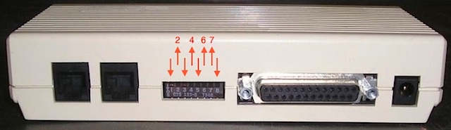
Dip Switches: 1, 3, 5 & 8 are DOWN. 2, 4, 6 & 7 are UP
➤ The following programming is for the MDR-2000 (CDR buffer) only:
  AT&F
  AT&M0&W&W1
The &M0 will disable error control (ARQ), &W&W1 will write it to both profiles.
➤ The following programming is for the SDI port on the Meridian 1 only:
  AT&F
  AT&B1&W&W1
The &B1 fixes the serial port rate (ie, not variable).
Note: When entering these commands your communications software must be set at the same baud rate as the SDI port on the Meridian 1. ie, if the SDI port is programmed for 1200,7,E, your communications software has to be set for 1200 baud.
Once the programming is done for either the MDR-2000 or the SDI port, the DIP switches on the back of the modem have to be set to the following:
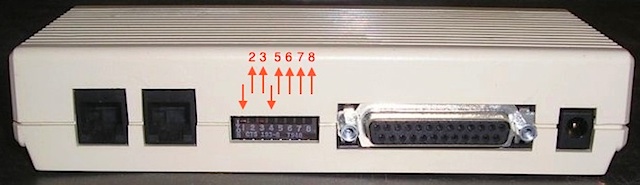
DIP switches: 1 & 4 DOWN. 2, 3, 5, 6, 7 & 8 UP
Description of DIP switch settings:
| Switch | Position | Function |
|---|---|---|
| 1 | Down ↓ | Modem Ignors DTR |
| 2 | Up ↑ | Verbal Result Codes |
| 3 | Up ↑ | Suppress Result Codes |
| 4 | Down ↓ | No echo, off-line commands |
| Switch | Position | Function |
|---|---|---|
| 5 | Up ↑ | Auto answer on first ring |
| 6 | Up ↑ | Carrier detect Normal |
| 7 | Up ↑ | Load NVRAM defaults |
| 8 | Up ↑ | Dumb mode |
U.S. Robotics 14.4 Sportster Vi Fax Modem
with Personal Voice Mail
The Sportster Vi models are a little different from the original Sportsters. They DO NOT have any dip switches on them so they have to be programmed differently. The following is the setup for the MDR-2000 and the M1.
➤ The following programming is for the MDR-2000 (CDR buffer) only:
  AT&F
  AT&M0S0=1&W&W1
The &M0 will disable error control (ARQ), S0=1 sets Auto Answer to 1 ring, and &W&W1 will qrite it to both profiles.
➤ The following programming is for the SDI port on the Meridian 1 only:
  AT&F
  ATX0&D0&H0&K0&M0S0=1E0Q1&W&W1
The X0 sets the result codes displayed, &D0 overrides DTR, &H0 dissables flow control, &K0 disables Data compression, &M0 disables Error control, S0=1 sets Auto Answer to 1 ring, E0 Echo off, Q1 is Quiet mode, no result codes, and &W&W1 will write it to both profiles.