Installing the PCCIU
Meridian 1 PC Console Interface Unit
The PC-based Console application software must be installed before the PCCIU is installed. Troubleshooting tips are below.
Installing the PCCIU:
- Place the PCCIU flat under the PC monitor with the front panel facing forward.
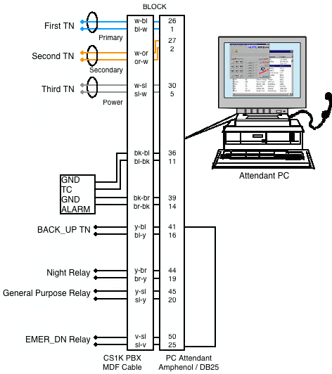
- Meridian 1 connector: connect a DB25 system cable to the MDF connector.
TN1: pair-1 (white/blue), TN2: pair-2 (white/orange), TN3 (PWR): pair-5 (white/slate) (>100m) - PC: connect a DB9 RS-232 serial cable to the serial port on the Attendant PC.
The supplied 9 pin cable connects to a PC COM port or Belkin USB-Serial adapter without a NULL modem.

- Attach a headset to the RJ32 jack or a handset to the PJ327 two-prong connector jack on either side of the PCCIU.
Ensure that the brandline plate on the handset connector jack faces forward. - Optional: connect the Power Fail Transfer pair (pairs 11 and 36) from the MDF block to the PFTU.
- Optional: connect a M3900 (digital telephone) to the PHONE connector. Must
also connect on the MDF block (BACK_UP).
Note: The M3900 can be used as a Night DN or as a backup telephone if the PC fails. - Optional: Connect the Night, General_Purpose, and EMER_DN relays to the MDF block.
Note: LDN0 must be configured with EMER_DN for this relay to work properly. - Optional: Use the Audio Input/Output jacks to connect third-party audio applications, if any.

The remaining ground, relay, & TN connections are optional.
Note: Power TN is not needed for cable runs under 100m.
Configuring the PCCIU:
- Ensure that there are three free ports on the digital line card (or four if you've optionally installed a M3900 Telephone).
- In LD 12, configure the first two units as the Primary and Secondary Terminal Numbers (TN's). Programming is the same as the M2250: enter 2250 at the TYPE prompt. Configure the third unit as a Power unit (TYPE: PWR).
- Optional: In LD 11, configure the fourth unit as a NIGHT_DN / BACKUP_DN (if you installed a M3900 Telephone).
- Optional: If you are using a PFTU, configure a free analog line card port in LD 10
Troubleshooting
Self-test and diagnostics:
When the PCCIU powers up, it performs a self-test diagnostic routine:
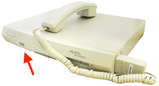
- The Status LED on the front of the PCCIU turns red for two seconds and then turns solid green.
- The Diagnostics LEDs on the back panel of the PCCIU flashes once and then turns off.
If a failure occurs during the self-test, the Status LED changes to yellow and the error is indicated by the illuminated Diagnostics LEDs.
Note: Only one error is indicated at a time, in priority order from highest (1) to lowest (7).
| Diagnostic LED | |||||
|---|---|---|---|---|---|
| 1 | 2 | 3 | 4 | Description | Priority |
| Self-test passed | - | ||||
| EEPROM failure | 7 | ||||
| Alerter micro failure | 6 | ||||
| Port expander failure | 5 | ||||
| Loopback test failure | 4 | ||||
| Secondary codec failure | 3 | ||||
| Primary codec failure | 2 | ||||
| RAM failure | 1 | ||||

Troubleshooting the Status LED:
The front-panel Status LED indicates the following:
- Normal condition, the PCCIU is working properly ✓
- There is no power getting to the PCCIU (from the PBX, on TN3)
-Check the DB25 system cable and the cross-connect wiring at the MDF. - Major alarm, a system-related error has occurred on the Meridian 1 PBX.
-Disable and re-enable both PC Console TN's (TN1 and TN2) in LD 32 (PRT, TYPE: 2250). - Indicates one of the following:
-PCCIU is in Night Service or Position Busy - check software Busy setting.
-Power Fail Transfer (PFT) is enabled - set the PFT switch OFF (1 = On, 0 = Off).
-Handset not connected properly - the brandline plate on the handset connector jack must face forward. - The PCCIU is not communicating with the PC properly.
-Ensure that the DB9 RS-232 serial cable is connected to the correct port.
-If the cable is connected properly but the Status LED remains red, run the >Standalone test procedure. - A failure occurred during the PCCIU self-test diagnostic routine.
Stand-alone test procedure:
This procedure has been know to revive a non-responding PCCIU!
- Disconnect the DB25 system cable to power down the PCCIU, disconnect the DB9 serial cable.
- Loop pins 2 and 3 on the PC port at the back of the PCCIU unit (or use a DB9 connector with pins 2 &3 shorted).
- Power up the PCCIU by reconnecting the DB25 system cable. Press the reset button at the back of the unit.
IMPORTANT!
- The reset button should only be used with pins 2 and 3 shorted.
- The PCCIU runs its self-test diagnostics and goes into run mode.
- The Status LED goes yellow if the Diagnostics LED's show a fault.
- Disconnect the DB25 system cable to power down the PCCIU. Reconnect the DB9 serial and DB25 system cables.
- If the PCCIU still fails to communicate with the PC, check the DB9 serial cable and the PC COM port settings.
Position Busy:
Clicking 'Busy' should activate the console, if not, check the COM port, PFTU switch, and handset.
PC failure:
In the event of PC failure, or loss of synchronization/communication between the PC and the PCCIU, there is no alarm or event indication. The PCCIU Status LED will still show solid green and calls will still present to the console. To remove the console from service until the PC function is restored, activate the Power Fail Transfer (PFT) switch or remove the headset or handset.


