Option 11C Cards
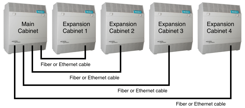
An Option 11C PBX consists of a Main cabinet and up to four expansion cabinets, (1-5 cabinets / 10-50 card slots). Any of the expansion cabinets can be located up to 3 km (1.8 miles) from the main cabinet using fiber optic cable or 100BaseT/F cable. From release 24, the maximum number of expansion cabinets increased from 2 to 4 with the introduction of dual port Fiber Daughter boards.
Small System Controller (SSC):
SSC Card NTDK20: Located in the Main cabinet card slot 0, the SSC card handles all the call processing for the system. Included on the card is an Ethernet controller, storage for system and customer data and system memory. Additional memory stores and processes automated routines and user-programmed routines. It retains a copy of customer files on a flash drive in the event of data loss.
Reload RAM: From the SSC primary Flash Drive can be done three different ways:
- LD 143, XSL (password= OHNO)
- or Power down the 11C, then power back up.
- or Push the SSC Initialize Button five times within a 24 hour period.
Drives in the Option 11C:
| A: PCMCIA Archive | C: Primary Flash Drive on the SSC card |
| B: PCMCIA Backup | Z: Secondary Flash Drive on Software Daughter board |
SSC/Card 0 Components:
- Software Daughter interface
- Two Fiber Expansion daughterboards
- Two PCMCIA interface slots
- Three SDI ports and one Ethernet port
- Security Device socket
- Reset button for Initializations
- Tone Digit Switch/Digittone Receiver:
- 8 channels of Tone Detection and
- 30 channels of Tone Generation
- 8 additional Tone Det. or 4 MFC/MFR - Conferencing-32 chan. (loop 29)
SSC Software Daughterboard NTSK03AQ: The system and customer data is stored on the Software Daughterboard attached to the SSC card. It comes preconfigured for new Option 11C installations (a PCMCIA card is not used to load the default data for new installs).
SSC PCMCIA Interface: The SSC card has a two-slot PCMCIA interface socket on its faceplate. Drive A is used for software upgrades. Drive B is used for creating an external backup copy of the customer data base (LD43 BKO).
SSC Fiber Expansion Daughterboards: Connects to Fiber Receiver cards on Expansion cabinets. Each dual port daughter board provides an additional 32 conference channels. The 1st daughter bd. connects to cabinets 1 & 3, the 2nd to cabinets 2 & 4.
SSC SDI ports: The default settings on the three SSC card serial data ports are:
| TTY Port | Baud rate | Data bits | Stop bits | Parity |
|---|---|---|---|---|
| 0 | SSC DIP switch | 8 | 1 | None |
| 1 | (1200)-64000 | 8 | 1 | None |
| 2 | (1200)-64000 | 8 | 1 | None |
SSC Conferencing: The SSC card provides 32 conferencing channels on loop 29. This capacity can be increased by adding Fiber Expansion daughter boards.
SSC Digittone Receiver, Tone Generation and Tone Detection functions: The SSC card provides 30 channels (loop 0) of tone and digit switch (TDS) tone generation, eight Digitone receivers (DTR) or dial tone detectors (XTD) and an additional 8 DTR/XTD or 4 MFC/MFR.
Optional Cards:
Serial Data Interface Card SDI/DCH NTAK02BB: Optional card that provides four additional SDI ports which can be used for either of the following:
- D-channel handler interface in ISDN applications
- Additional DTE or DCE devices for applications like Call Detail Reporting or Traffic Studies or ACD MAX Reports.
TDS/DTR NTAK03: Adds 30 tone transmission & 8 tone detection channels + two SDI ports.
Digital Trunk card (DTI/PRI 1.5Mb) NTAK09. And three optional daughter boards:
- NTAK20 Clock Controller
- NTAK93 D-Channel Interface
- NTBK51 DDCH
Digital Trunk Package: NTSF6800 TMDI Hardware Package (1.5MB DTI/PRI) includes:
- 1 1.5 MB DTI/PRI/TMDI Administration and Maintenance Guide
- 1 T1 Multipurpose Digital Interface (TMDI) Card (NTRB21AB)
- 1 DTI/PRI Cable (NTBK04AA)
Note: Also required for PRI trunks is the "NTSF8730 TMDI D-Channels Software Package", which has D-Channel ISM parameters in increments of 1 per package. Since release 25.3, DTI/PRI can be installed in expansion cabinets-not limited to main cab.
Fiber Receiver card: Install in the first slot of each expansion cabinet. Connects an expansion cabinet to the main cabinet. Additionally, each Fiber Receiver card provides one SDI port for remote TTY access.
- 10 Meter, NTDK23: Supports a plastic fiber cable connection
- 3 Kilometer, NTDK25 or NTDK80: Supports a glass fiber cable connection.
Call Pilot 201i Card NTRH30AA: Installs in slots 9 and 10, provides up to 40 channels.
Meridian Mail Card NT6R16AA: Installs in slot ten and provides 4 Voice Mail ports. One or two optional NTMW03AA daughter boards add 4-8 Voice Mail ports. Each Meridian Mail port is matched with a Meridian 1 ACD agent:
| Meridian ACD Agents (LD 11, Type=2008) | Meridian Mail Ports | ||||||||
| DES | TN | Key 0 | Key 1 | Port | C | D | P | ACDN | |
|---|---|---|---|---|---|---|---|---|---|
| MMAGT1 | 10 0 00 00 | 5555/7830 | 7800 | 5 | 4 | 1 | 1 | 5555 | Top Daughter Board |
| MMAGT2 | 10 0 00 08 | 5555/7831 | 7801 | 6 | 4 | 1 | 2 | 5555 | |
| MMAGT3 | 10 0 00 01 | 5555/7832 | 7802 | 7 | 4 | 2 | 1 | 5555 | |
| MMAGT4 | 10 0 00 09 | 5555/7833 | 7803 | 8 | 4 | 2 | 2 | 5555 | |
| MMAGT5 | 10 0 00 04 | 5000/7838 | 7808 | 1 | 3 | 1 | 1 | 5000 | Main Mail Card |
| MMAGT6 | 10 0 00 12 | 5000/7839 | 7809 | 2 | 3 | 1 | 2 | 5000 | |
| MMAGT7 | 10 0 00 05 | 5000/7840 | 7810 | 3 | 3 | 2 | 1 | 5000 | |
| MMAGT8 | 10 0 00 13 | 5000/7841 | 7811 | 4 | 3 | 2 | 2 | 5000 | |
Key: C = Card, D = DSP Digital Signal Processor, P = Port
Line and Trunk Cards:
The same phone and analog trunk cards are used in all of the Meridian PBX switches (11C-81C). If all the circuits on a line card are removed (OUTed), the card will be taken out of service (an INI maybe required), it's red alarm LED will light, and the PBX will assume that the slot is vacant.
Analog Message Waiting Line Card NT8D09: Analog-to-digital and digital-to-analog conversion for 16 analog telephones (units 0-15) with 600 ohm balanced terminating impedance. Message Waiting is provided by pulsating 150VDC. Loop resistance and phone resistance should not be greater than 600 ohms. Good up to two miles. Also available is the NT1R20 OPX eight-circuit line card--capable of distances up to five miles or 1400 ohms of loop resistance.
Analog Line Card NT8D09BA: Supports 56K and V.90 throughput. This allows you to dial through the switch and get a 56K analog modem connection. Previous analog cards would only allow 28.8 connection speeds.
Digital Line Card NT8D02: 16 voice units (0-15) and 16 data units/card (16-31) each with 64 Kbits of bandwidth. The distance limit (loop length) with 24 AWG wire is 1067 meters (180 ohms loop resistance) with the 2000 and 3900 series of phones. The set itself has 100 ohm impedance. Audio/digital conversion is made at the set. The data port requires a data module on the set.
E&M Trunk Card NT8D15: Any combination of four analog E&M trunks (units 0-3) that are configured independently by programming in Load 14. Configuration options include 2 or 4 wire, and Type 1 or 2. The 4 wire E&M has four leads for voice transmission: TA and TB for output, RA and RB for input. E and M signaling is accomplished using the E and M leads.
Universal Trunk Card NT8D14AA: Supports eight trunks (units 0-7) in any combination of six trunk types: CO, DID, TIE, Recorded Announcement (RAN), Paging and Music (MOH). Terminating impedance is software selectable between 600 ohm, 900 ohm or 3COM (LD 14, TIMP or BIMP). Signaling range, on a central office trunk, to the exchange is 1700 ohms loop resistance. After making any changes to the route data block, trunk cards must be downloaded by using Load 32's ENLC l s c (enable loop/shelf/card) command. When the Trunk Failure Monitor (TFM) package #182 is enabled, a failed trunk is displayed as busy. Disable or enable trunks in Load 32. Note: When Universal trunks are cabled out at the MDF, every other pair is skipped-trunk unit 0 is on pair one; unit 1 is on pair 3; unit 2 is on pair 5; etc.
Source: Nortel Training Documentation.